![[Digital logo]](../../IMAGES/DIGITAL-LOGO.GIF)
![[HR]](../../IMAGES/REDBAR.GIF)
![[Digital logo]](../../IMAGES/DIGITAL-LOGO.GIF)
![[HR]](../../IMAGES/REDBAR.GIF)
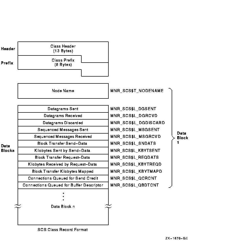
Figure H-21 illustrates the format of the SCS class record. Table H-21 describes the fields in the data block for the SCS class record.
Figure H-21 SCS Class Record Format
| Field | Symbolic Offset | Contents |
|---|---|---|
| Node Name | MNR_SCS$T_NODENAME | Name of remote cluster node (counted ASCII string) (8 bytes,I) |
| Datagrams Sent | MNR_SCS$L_DGSENT | Count of datagrams sent to the remote node (longword,C) |
| Datagrams Received | MNR_SCS$L_DGRCVD | Count of datagrams received from the remote node (longword,C) |
| Datagrams Discarded | MNR_SCS$L_DGDISCARD | Count of datagrams discarded by the CI port driver (longword,C) |
| Sequenced Messages Sent | MNR_SCS$L_MSGSENT | Count of sequenced messages sent to the remode node (longword,C) |
| Seqenced Messages Received | MNR_SCS$L_MSGRCVD | Count of sequenced messages received from the remote node (longword,C) |
|
Block Transfer
Send-data commands |
MNR_SCS$L_SNDATS | Count of block transfer send-data commands initiated on the local node, targeted for the remote node (longword,C) |
|
Kilobytes Sent by
Send-data commands |
MNR_SCS$L_KBYTSENT | Count of kilobytes sent as a result of send-data commands (longword,C) |
|
Block Transfer Request-
data commands |
MNR_SCS$L_REQDATS | Count of block transfer request-data commands initiated on the local node, targeted for the remote node (longword,C) |
|
Kilobytes Received by
Request-data commands |
MNR_SCS$L_KBYTREQD | Count of kilobytes received as a result of request-data commands (longword,C) |
|
Block Transfer
Kilobytes Mapped |
MNR_SCS$L_KBYTMAPD | Count of kilobytes mapped for block transfers (longword,C) |
|
Connections Queued For
Send Credit |
MNR_SCS$L_QCRCNT | Count of times connections are queued for send credits (longword,C) |
|
Connections Queued For
Buffer Descriptor |
MNR_SCS$L_QBDTCNT | Count of times connections are queued for buffer descriptors (longword,C) |
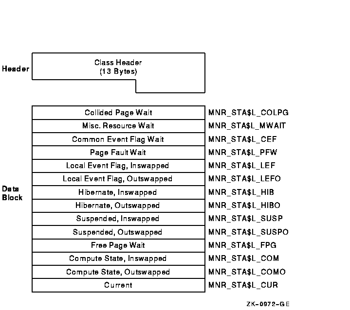
The STATES class record contains data describing the number of processes in each of the scheduler states. The STATES class record has a record type of 1 and a size of 69 bytes.
Figure H-22 illustrates the format of the STATES class record. Table H-22 describes the fields in the data block for the STATES class record.
Figure H-22 STATES Class Record Format
| Field | Symbolic Offset | Contents |
|---|---|---|
|
Collided
Page Wait |
MNR_STA$L_COLPG | Number of processes in collided page wait (longword,L) |
|
Misc
Resource Wait |
MNR_STA$L_MWAIT | Number of processes in miscellaneous resource wait (longword,L) |
|
Common Event
Flag Wait |
MNR_STA$L_CEF | Number of processes in common event flag wait (longword,L) |
|
Page Fault
Wait |
MNR_STA$L_PFW | Number of processes in page fault wait (longword,L) |
|
Local Event Flag,
Inswapped |
MNR_STA$L_LEF | Number of processes in local event flag wait, inswapped (longword,L) |
|
Local Event Flag,
Outswapped |
MNR_STA$L_LEFO | Number of processes in local event flag wait, outswapped (longword,L) |
|
Hibernate,
Inswapped |
MNR_STA$L_HIB | Number of processes in hibernate wait, inswapped (longword,L) |
|
Hibernate,
Outswapped |
MNR_STA$L_HIBO | Number of processes in hibernate wait, outswapped (longword,L) |
|
Suspended,
Inswapped |
MNR_STA$L_SUSP | Number of processes in suspended wait, inswapped (longword,L) |
|
Suspended,
Outswapped |
MNR_STA$L_SUSPO | Number of processes in suspended wait, outswapped (longword,L) |
|
Free Page
Wait |
MNR_STA$L_FPG | Number of processes in free wait (longword,L) |
|
Compute State,
Inswapped |
MNR_STA$L_COM | Number of processes in compute state, inswapped (longword,L) |
|
Compute State,
Outswapped |
MNR_STA$L_COMO | Number of processes in compute state, outswapped (longword,L) |
| Current | MNR_STA$L_CUR | Number of current processes (longword,L) |
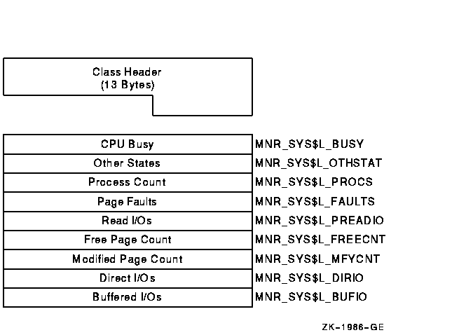
The SYSTEM class record contains data describing the overall operation of the three major system components (CPU, memory, I/O). The SYSTEM class record has a record type of 17 and a size of 49 bytes. Note that when the SYSTEM class is recorded, the PROCESSES, STATES, and MODES classes are also recorded, even if not explicitly requested.
Figure H-23 illustrates the format of the SYSTEM class record. Table H-23 describes the fields in the data block for the SYSTEM class record.
Figure H-23 SYSTEM Class Record Format
| Field | Symbolic Offset | Contents |
|---|---|---|
| CPU Busy | MNR_SYS$L_BUSY | Count of clock ticks (10-millisecond units) spent in all CPU modes since system was booted (longword,C) |
| Other States | MNR_SYS$L_OTHSTAT | Number of processes in states other than LEF, LEFO, HIB, HIBO, COM, COMO, PFW, and MWAIT (longword,L) |
| Process Count | MNR_SYS$L_PROCS | Number of processes in system (longword,L) |
| Page Faults | MNR_SYS$L_FAULTS | Count of page faults for all working sets (longword,C) |
| Read I/Os | MNR_SYS$L_PREADIO | Count of read I/Os resulting from disk page faults (longword,C) |
| Free Page Count | MNR_SYS$L_FREECNT | Number of pages currently on free-page list (longword,L) |
| Modified Page Count | MNR_SYS$L_MFYCNT | Number of pages currently on modified-page list (longword,L) |
| Direct I/Os | MNR_SYS$L_DIRIO | Count of direct I/O operations (longword,C) |
| Buffered I/Os | MNR_SYS$L_BUFIO | Count of buffered I/O operations (longword,C) |
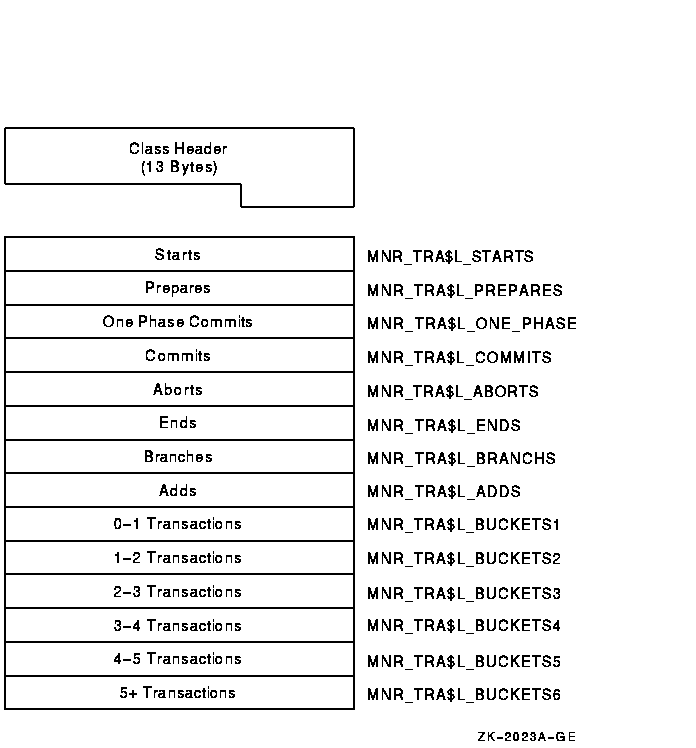
The TRANSACTION class record contains data describing the operations of the DECdtm transaction manager. The TRANSACTION class has a record type of 22 and a size of 69 bytes. Figure H-24 illustrates the format of the TRANSACTION class record. Table H-24 describes the contents of each of its fields.
Figure H-24 TRANSACTION Class Record Format
| Field | Symbolic Offset | Contents |
|---|---|---|
| Starts | MNR_TRA$L_STARTS | Count of transactions started. The number of times that calls on the local node to $START_TRANS have completed successfully (longword, C). |
| Prepares | MNR_TRA$L_PREPARES | Count of transactions that have been prepared (longword, C). |
| One Phase Commits | MNR_TRA$L_ONE_PHASE | Count of one-phase commit events initiated (longword, C). |
| Commits | MNR_TRA$L_COMMITS | Count of transactions committed. This is the combined total of one-phase and two-phase commits (longword, C). |
| Aborts | MNR_TRA$L_ABORTS | Count of transactions aborted. Combined total of planned and unplanned aborts (longword, C). |
| Ends | MNR_TRA$L_ENDS | Count of transactions ended. The number of times that calls on the local node to $END_TRANS have completed successfully (longword, C). |
| Branches | MNR_TRA$L_BRANCHS | Count of transaction branches started on the local node (longword, C). |
| Adds | MNR_TRA$L_ADDS | Count of transaction branches added on the local node (longword, C). |
| 0-1 Transactions | MNR_TRA$L_BUCKETS1 | Count of transactions with a duration of less than 1 second (longword, C). |
| 1-2 Transactions | MNR_TRA$L_BUCKETS2 | Count of transactions with a duration of 1 to 2 (1.99) seconds (longword, C). |
| 2-3 Transactions | MNR_TRA$L_BUCKETS3 | Count of transactions with a duration of 2 to 3 seconds (longword, C). |
| 3-4 Transactions | MNR_TRA$L_BUCKETS4 | Count of transactions with a duration of 3 to 4 seconds (longword, C). |
| 4-5 Transactions | MNR_TRA$L_BUCKETS5 | Count of transactions with a duration of 4 to 5 seconds (longword, C). |
| 5+ Transactions | MNR_TRA$L_BUCKETS6 | Count of transactions with a duration greater than 5 seconds (longword, C). |
H.4.2.18 VBS Class Record (VAX Only)
On VAX systems, the VBS class record contains statistics on the
operation of the virtual balance slot (VBS) mechanism. The VBS class
record has a record type of 24 and a size of 21 bytes.
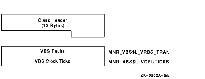
Figure H-25 illustrates the format of a VBS class record. Table H-25 describes the fields in the data block for the VBS class record.
Figure H-25 VBS Class Record Format (VAX Only)
| Field | Symbolic Offset | Contents |
|---|---|---|
| VBS Faults | MNR_VBS$L_VRBS_TRAN | Count of faults from virtual balance slots to real balance slots (longword, C) |
| VBS Clock Ticks | MNR_VBS$L_VCPUTICKS | Count of virtual balance slot clock ticks (10-millisecond units) (longword, C) |
H.4.2.19 VECTOR Class Record
The VECTOR class record contains data describing the time during which
vector consumers have been scheduled on a vector-present processor. Its
record type number is 23. A VECTOR class record is of variable length
and depends on the number of active processors in the system. Assuming
all processors are active, MONITOR calculates the size of the record by
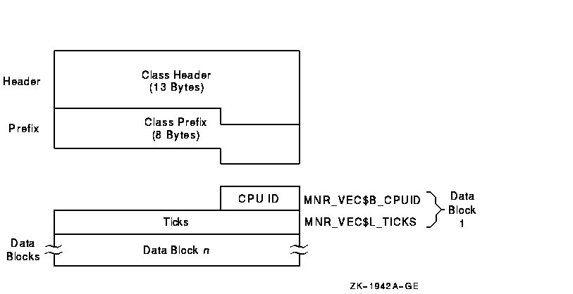
adding the size of the class header, the class prefix, and the data
blocks contained in the record. This is shown in the following formula:
13 + 8 + (5 * MNR_SYI$B_VPCPUS)
Figure H-26 illustrates the format of the VECTOR class record. Table H-26 describes the contents of each of its fields.
Figure H-26 VECTOR Class Record Format
| Field | Symbolic Offset | Contents |
|---|---|---|
| CPU ID | MNR_VEC$B_CPUID | Identification of the processor from which the data has been collected (byte, I) |
| Ticks | MNR_VEC$L_TICKS | Number of 10-millisecond clock ticks in which a vector consumer has been scheduled on this processor (longword, C) |
To support the VECTOR class, MONITOR uses the items MNR_SYI$B_VPCPUS and MNR_SYI$L_VPCONF in the system information record. See Table H-3 for details on these items.
SHOW CLUSTER provides a predefined keypad that you can use to enter
selected commands. You can add, remove, or reposition windows, scroll
their contents, or change the interval at which the display is updated.
You can also customize the keypad by redefining the default functions
of individual keys.
I.1 Using the Keypad
By default, the numeric keypad is defined as shown in Figure I-1.
Figure I-1 SHOW CLUSTER Default Keypad
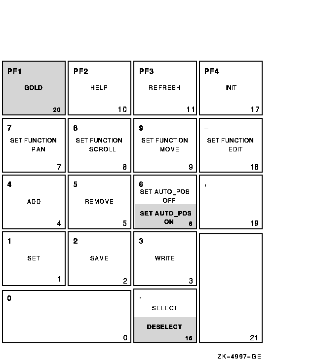
Shading over a keypad command indicates that you must press the GOLD key and then the keypad key.
Table I-1 describes each of the keypad commands you can use with the Show Cluster utility. In this table, KPn refers to the keypad key labeled with the number n. For example, KP2 refers to the keypad key labeled with the number 2. All commands shown on the keypad are also discussed in the Command Section of Chapter 18.
| Command | Key or Key Sequence |
Description |
|---|---|---|
| ADD | KP4 | Modifies the current display by including the field or class that you specify after the ADD command. |
| DESELECT | GOLD-Period | Terminates a window selection. |
| GOLD | PF1 | When pressed before another keypad key, specifies the second key's alternate function (the bottom function on the keypad diagram). |
| HELP | PF2 | Displays information about using the editing keypad. |
| INIT | PF4 | Resets the display using the original default values for field names, class names, and field widths. |
| REFRESH | PF3 | Refreshes the screen display. Clears and redraws the screen, deleting any extraneous characters or messages that might have appeared on the screen but are not part of the SHOW CLUSTER display. (Performs the same function as Ctrl/W.) |
| REMOVE | KP5 | Modifies the current display by removing the field or class that you specify after the REMOVE command. |
| SAVE | KP2 | Allows you to save the current display to a startup initialization file or a command procedure that you can then use to restore the display at a later time. |
| SELECT | Period | Designates which window to scroll or move. |
| SET | KP1 | Changes any of several options including the number of columns in the display, the number of seconds between updates, the functions of the arrow keys, the auto positioning of windows, and the characteristics of a particular field. |
| SET AUTO_POS OFF | KP6 | Disables the automatic positioning of windows on the screen. |
| SET AUTO_POS ON | GOLD-KP6 | Enables the Show Cluster utility to automatically position windows on the screen. This is the default setting. |
|
SET FUNCTION
EDIT |
Hyphen | Redefines the arrow keys to restore line-mode editing. |
|
SET FUNCTION
MOVE |
KP9 | Redefines the arrow keys to move a selected window to a specified position on the display screen. For example, the UP, DOWN, RIGHT, and LEFT arrow keys are redefined as MOVE UP 1, MOVE DOWN 1, MOVE RIGHT 1, and MOVE LEFT 1, respectively. |
|
SET FUNCTION
PAN |
KP7 | Redefines the arrow keys to rotate the display. For example, the UP, DOWN, RIGHT, and LEFT arrow keys are redefined as PAN UP 1, PAN DOWN 1, PAN RIGHT 1, and PAN LEFT 1, respectively. |
|
SET FUNCTION
SCROLL |
KP8 | Resets the arrow keys to scroll the screen display. For example, if you press the SET FUNCTION SCROLL key, the UP, DOWN, RIGHT, and LEFT arrow keys are redefined as SCROLL UP 1, SCROLL DOWN 1, SCROLL RIGHT 1, and SCROLL LEFT 1, respectively. |
| WRITE | KP3 | Outputs the current display to either a file name that you specify, or to the default output file name SHOW_CLUSTER.LIS. |
Use the DEFINE/KEY command to change the definition of a key. See the
DEFINE/KEY command in the Command Section of Chapter 18 for more
information.
I.3 Redefining the Arrow Keys
By default, the SHOW CLUSTER arrow keys are set to the EDIT function. This means that you can perform command line editing at the command prompt that is similar to DCL line-mode editing. For example, the left arrow key moves the cursor to the left, or the up arrow key recalls the previous command. See the OpenVMS User's Manual for information on DCL line-mode editing.
The SET FUNCTION keys, shown in the second row of the keypad, redefine the arrow keys to perform a specified function. You can reset the arrow keys from EDIT to PAN, SCROLL, or MOVE with the SET FUNCTION command. For example, if you press the SET FUNCTION SCROLL key, the up, down, right, and left arrow keys are redefined as SCROLL UP 1, SCROLL DOWN 1, SCROLL RIGHT 1, and SCROLL LEFT 1, respectively. (See the Command Section of Chapter 18 for information on specific commands.)
Note
If you set the function to PAN, SCROLL, or MOVE, the arrow keys are no longer defined to perform DCL line-mode editing. Only one function can be enabled at a time. To restore line-mode editing once it has been changed to another function, enter the command SET FUNCTION EDIT.
This appendix describes OpenVMS system parameters.
Note
Digital recommends that you use AUTOGEN to modify system parameters. In special cases, however, you can use a conversational boot to modify a parameter value temporarily. To change a parameter value permanently, you must edit MODPARAMS.DAT and run AUTOGEN. For instructions, see the OpenVMS System Manager's Manual.
System parameters can be grouped into categories, as shown in Section J.1.1. In addition, each parameter can have one or more attributes, listed in Section J.1.1. Each parameter also has a value.
The parameters in this appendix are listed alphabetically along with
their attributes.
J.1.1 Parameter Categories and Attributes
The system parameters can be divided into the following categories (see also Table J-1):
| Category | Description |
|---|---|
| ACP | Parameters associated with file system caches and Files-11 ancillary control processes (ACPs) |
| CLUSTER | Parameters that affect OpenVMS Cluster operation |
| JOB | Job control parameters |
| LGI | Login security parameters |
| PQL | Parameters associated with process creation limits and quotas |
| RMS | Parameters associated with OpenVMS RMS |
| SCS | Parameters that control System Communications Services (SCS) and port driver operation. The parameters that affect SCS operation have the prefix SCS. The parameters that affect the CI780/CI750 port driver have the prefix PA. |
| SPECIAL | Special parameters used by Digital. These parameters should only be changed if recommended by Digital personnel, or if they are clearly stated to change in the installation guide or release notes of a Digital-supplied layered product. Section J.2.2 describes the special parameters. |
| SYS | Parameters that affect overall system operation |
| TTY | Parameters associated with terminal behavior |
The user can also define four parameters: USERD1, USERD2, USER3, and USER4. USERD1 and USERD2 are dynamic.
Attributes for Parameters
Parameters can have one or more of the following attributes:
| Attribute | Description |
|---|---|
| AUTOGEN | AUTOGEN calculates and modifies values |
| DYNAMIC | Active values can be modified |
| FEEDBACK | FEEDBACK information available for AUTOGEN calculations |
| GEN | Affects the creation and initialization of data structures at bootstrap time |
| MAJOR | Most likely to require modification |
Table J-1 lists system parameters according to category. Footnotes indicate dynamic and system-specific parameters.
| ACP Parameters | ||
|---|---|---|
| ACP_BASEPRIO¹ | ACP_DATACHECK¹ | ACP_DINDXCACHE¹ |
| ACP_DIRCACHE¹ | ACP_EXTCACHE¹ | ACP_EXTLIMIT¹ |
| ACP_FIDCACHE¹ | ACP_HDRCACHE¹ | ACP_MAPCACHE¹ |
| ACP_MAXREAD¹ | ACP_MULTIPLE¹ | ACP_QUOCACHE¹ |
| ACP_REBLDSYSD | ACP_SHARE¹ | ACP_SWAPFLGS¹ |
| ACP_SYSACC¹ | ACP_WINDOW¹ | ACP_WORKSET¹ |
| ACP_WRITEBACK¹ | ACP_XQP_RES¹ | |
| CLUSTER Parameters | ||
| ALLOCLASS | +CHECK_CLUSTER | CLUSTER_CREDITS |
| DISK_QUORUM¹ | DR_UNIT_BASE | EXPECTED_VOTES |
| LOCKDIRWT | MSCP_BUFFER | MSCP_CMD_TMO |
| MSCP_CREDITS | MSCP_LOAD | MSCP_SERVE_ALL |
| NISCS_CONV_BOOT | NISCS_LOAD_PEA0 | NISCS_PORT_SERV |
| QDSKINTERVAL | QDSKSVOTES | RECNXINTERVAL¹ |
| TAPE_ALLOCLASS | TMSCP_LOAD | TMSCP_SERVE_ALL |
| VAXCLUSTER | VOTES | |
| JOB Parameters | ||
| DEFPRI¹ | DEFQUEPRI¹ | IJOBLIM¹ |
| MAXQUEPRI¹ | NJOBLIM¹ | RJOBLIM¹ |
| LGI Parameters | ||
| LGI_BRK_DISUSER¹ | LGI_BRK_LIM¹ | LGI_BRK_TERM¹ |
| LGI_BRK_TMO¹ | LGI_CALLOUTS¹ | LGI_HID_TIM¹ |
| LGI_PWD_TMO¹ | LGI_RETRY_LIM¹ | LGI_RETRY_TMO¹ |
| MULTIPROCESSING Parameters | ||
| ++IO_PREFER_CPUS | MULTIPROCESSING | SMP_CPUS |
| SMP_LNGSPINWAIT | SMP_SANITY_CNT | SMP_SPINWAIT |
| PQL Parameters | ||
| PQL_DASTLM¹ | PQL_DBIOLM¹ | PQL_DBYTLM¹ |
| PQL_DCPULM¹ | PQL_DDIOLM¹ | PQL_DENQLM¹ |
| PQL_DFILLM¹ | PQL_DJTQUOTA | PQL_DPGFLQUOTA¹ |
| PQL_DPRCLM¹ | PQL_DTQELM¹ | PQL_DWSDEFAULT |
| PQL_DWSEXTENT¹ | PQL_DWSQUOTA¹ | PQL_MASTLM¹ |
| PQL_MBIOLM¹ | PQL_MBYTLM¹ | PQL_MCPULM¹ |
| PQL_MDIOLM¹ | PQL_MENQLM¹ | PQL_MFILLM¹ |
| PQL_MJTQUOTA | PQL_MPGFLQUOTA¹ | PQL_MPRCLM¹ |
| PQL_MTQELM¹ | PQL_MWSDEFAULT | PQL_MWSEXTENT¹ |
| PQL_MWSQUOTA¹ | ||
| RMS Parameters | ||
| RMS_DFMBC¹ | RMS_DFMBFIDX¹ | RMS_DFMBFREL¹ |
| RMS_DFMBFSDK¹ | RMS_DFMBFSMT¹ | RMS_DFMBFSUR¹ |
| RMS_DFNBC¹ | RMS_EXTEND_SIZE¹ | RMS_FILEPROT |
| RMS_PROLOGUE¹ | ||
| SCS Parameters | ||
| PAMAXPORT¹ | PANOPOLL¹ | PANUMPOLL¹ |
| PAPOLLINTERVAL¹ | PAPOOLINTERVAL¹ | PASANITY¹ |
| PASTDGBUF | PASTIMOUT¹ | PRCPOLINTERVAL¹ |
| SCSBUFFCNT | SCSCONNCNT | SCSFLOWCUSH¹ |
| SCSMAXDG | SCSMAXMSG | SCSNODE |
| SCSRESPCNT | SCSSYSTEMID | SCSSYSTEMIDH |
| TIMVCFAIL¹ | UDABURSTRATE | |
| Special Parameters | ||
| AFFINITY_SKIP | AFFINITY_TIME | BREAKPOINTS |
| CHANNELCNT | +CLOCK_INTERVAL | CONCEAL_DEVICES |
| +CRD_CONTROL | CTLIMGLIM | CTLPAGES |
| DISABLE_UPCALLS¹ | +DLCKEXTRASTK | DNVOSI1 |
| EXUSRSTK | ++FAST_PATH | IMGIOCNT |
| IOTA | JOBCTLD | LOAD_SYS_IMAGES |
| LOCKRETRY | MAXCLASSPRI¹ | MINCLASSPRI¹ |
| MPW_PRIO | NOAUTOCONFIG¹ | +NOCLUSTER |
| NOPGFLSWP | PAGTBLPFC | PE |
| ++PFN_COLOR_COUNT | ++PHYSICAL_MEMORY | +PHYSICALPAGES |
| PIOPAGES¹ | PIXSCAN¹ | POOLCHECK¹ |
| POOLPAGING | PRIORITY_OFFSET | +PSEUDOLOA |
| PU_OPTIONS | +QBUS_MULT_INTR | RESALLOC |
| RSRVPAGCNT | S0_PAGING | SA_APP |
| +SBIERRENABLE | +SCH_CTLFLAGS¹ | +SCSI_NOAUTO¹ |
| ++SCSICLUSTER_P[1-4] | SMP_CPUSH | SMP_TICK_CNT |
| SSINHIBIT | SWPALLOCINC | SWPFAIL |
| SWPRATE | SWP_PRIO | SYSPFC |
| TBSKIPWSL | TIME_CONTROL¹ | USERD1¹ |
| USERD2¹ | USER3 | USER4 |
| +VBN_CACHE_S | +VBSS_ENABLE | +VBSS_ENABLE2 |
| ++VCC_FLAGS | ++VCC_MAXSIZE | +VCC_PTES |
| VMS¹ | WPRE_SIZE¹ | WPTTE_SIZE¹ |
| WRITABLESYS | WRITESYSPARAMS¹ | XQPCTL2 |
| XQPCTLD1 | ||
| SYS Parameters | ||
| AWSMIN¹ | AWSTIME¹ | BALSETCNT |
| BORROWLIM¹ | BUGCHECKFATAL¹ | BUGREBOOT¹ |
| CLASS_PROT¹ | CLISYMTBL¹ | CRDENABLE |
| CWCREPRC_ENABLE | ++DBGTK_SCRATCH | DEADLOCK_WAIT¹ |
| DEFMBXBUFQUO¹ | DEFMBXMXMSG¹ | ++DEVICE_NAMING |
| DORMANTWAIT¹ | DUMPBUG | DUMPSTYLE¹ |
| ERLBUFFERPAGES | ERRORLOGBUFFERS | EXTRACPU¹ |
| FREEGOAL¹ | FREELIM | GBLPAGES¹ |
| GBLPAGFIL¹ | GBLSECTIONS | ++GH_EXEC_CODE |
| ++GH_EXEC_DATA | ++GH_RES_CODE | ++GH_RES_DATA |
| ++GH_RSRVPGCNT | GROWLIM¹ | ++IMGREG_PAGES |
| +INTSTKPAGES¹ | ++KSTACKPAGES | +LAMAPREGS |
| ++LAN_FLAGS¹ | LNMPHASHTBL | LNMSHASHTBL |
| LOAD_PWD_POLICY | LOCKIDTBL | LONGWAIT¹ |
| ++MAXBOBMEM | MAXBUF¹ | MAXPROCESSCNT |
| MAXSYSGROUP¹ | MC_SERVICES_P0 | MC_SERVICES_P1¹ |
| MC_SERVICES_P3 | MC_SERVICES_P4 | MC_SERVICES_P5¹ |
| MC_SERVICES_P6 | MC_SERVICES_P7¹ | MC_SERVICES_P8 |
| MC_SERVICES_P9 | MINWSCNT | MMG_CTLFLAGS¹ |
| MPW_HILIMIT | MPW_IOLIMIT | MPW_LOLIMIT |
| MPW_LOWAITLIMIT¹ | MPW_THRESH¹ | MPW_WAITLIMIT¹ |
| MPW_WRTCLUSTER | ++MULTITHREAD | MVTIMEOUT¹ |
| NET_CALLOUTS¹ | NISCS_LAN_OVRHD | NISCS_MAX_PKTSZ |
| NPAGEDYN | NPAGEVIR | NPAG_AGGRESSIVE¹ |
| NPAG_BAP_MAX | NPAG_BAP_MAX_PA | NPAG_BAP_MIN |
| NPAG_GENTLE¹ | NPAG_INTERVAL¹ | NPAG_RING_SIZE |
| PAGEDYN | PAGFILCNT | PFCDEFAULT¹ |
| PFRATH¹ | PFRATL¹ | PROCSECTCNT |
| QUANTUM¹ | +REALTIME_SPTS¹ | RESHASHTBL |
| ++S2_SIZE | SAVEDUMP | SECURITY_POLICY |
| SETTIME | SHADOWING | SHADOW_MAX_COPY¹ |
| SHADOW_MBR_TMO¹ | SHADOW_SYS_DISK | SHADOW_SYS_TMO |
| SHADOW_SYS_UNIT | SHADOW_SYS_WAIT | +SPTREQ |
| STARTUP_P1-8 | SWPFILCNT | SWPOUTPGCNT¹ |
| SYSMWCNT | SYSTEM_CHECK | TAILORED |
| TAPE_MVTIMEOUT¹ | TIMEPROMPTWAIT | UAFALTERNATE |
| +VECTOR_MARGIN¹ | +VECTOR_PROC | VIRTUALPAGECNT |
| WINDOW_SYSTEM¹ | WSDEC¹ | WSINC¹ |
| WSMAX | WS_OPA0 | XFMAXRATE¹ |
| ++ZERO_LIST_HI¹ | ||
| TTY Parameters | ||
| TTY_ALTALARM | TTY_ALTYPAHD | TTY_AUTOCHAR¹ |
| TTY_BUF | TTY_CLASSNAME | TTY_DEFCHAR |
| TTY_DEFCHAR2 | TTY_DEFPORT | TTY_DIALTYPE |
| TTY_DMASIZE¹ | TTY_PARITY | TTY_RSPEED |
| TTY_SCANDELTA | TTY_SILOTIME | TTY_SPEED |
| TTY_TIMEOUT¹ | TTY_TYPAHDSZ | |
Each parameter has associated default, minimum, and maximum values that define the scope of allowable values. To determine these values, invoke SYSGEN and enter a SHOW [parameter-name] command (with appropriate qualifiers). For example, to display the values for WSMAX, you can specify SHOW WSMAX; to display the values for the TTY parameters, you can specify SHOW/TTY. You can also display parameters grouped by attributes. To display DYNAMIC parameters, for example, specify SHOW/DYNAMIC.
![[HR]](../../IMAGES/REDBAR.GIF)
  6048P064.HTM
  OSSG Documentation
  26-NOV-1996 12:44:00.25
Copyright © Digital Equipment Corporation 1996. All Rights Reserved.