![[Digital logo]](../../IMAGES/DIGITAL-LOGO.GIF)
![[HR]](../../IMAGES/REDBAR.GIF)
![[Digital logo]](../../IMAGES/DIGITAL-LOGO.GIF)
![[HR]](../../IMAGES/REDBAR.GIF)
DECnet-Plus routing has an additional segmentation capability: if a packet is in the ISO 8473 packet format (the format used between DECnet-Plus systems), a DECnet-Plus router can segment it to fit the data-link size. The Routing layer of the destination system reassembles the segments before delivering the packet to the Transport layer. In contrast, a Phase IV router cannot segment packets to fit the data-link size. When forwarding a packet, a Phase IV router drops the packet if it is too large for the specific data link being used.
For a network in the transition, decide whether to:
To set a consistent network buffer size, use one of the following:
To change the IDP and preDSP of a network, follow these steps (waiting at least 24 hours between each step):
This chapter discusses the format of NSAP addresses for DECnet-Plus systems and describes how to get unique identification for your DECnet Phase V network. You need this information to:
The DECnet Phase V addressing scheme for DECnet-Plus nodes complies with the ISO 8348 Addendum 2 addressing standard. This scheme uses the concepts of global addressing, addressing authorities, and addressing domains. Global network addressing is an ISO scheme designed to provide unique network addresses throughout the world.
A global network address is called a network service access
point (NSAP). Because it is used to determine the destination
node for all packets, the NSAP must be unique for each node in a
network.

For more information about addressing and service access points (SAPs), refer to Chapter 3 of the DECnet-Plus for OpenVMS Introduction and User's Guide.<>
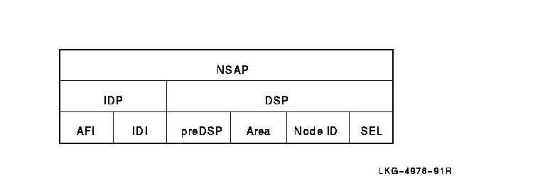
Some NSAP field values are assigned by an allocation authority, and some you assign yourself for your organization. Every NSAP has two primary fields:
Figure 4-1 shows the parts of an NSAP and network entity title (NET). To compare these parts with Phase IV addresses, see Table 1-1.
Figure 4-1 Parts of an NSAP

The IDP helps ensure that NSAP values are globally unique. For this reason, IDP values are assigned by recognized authorities or are based on another value (such as a Telex number) that has already been assigned by some authority.
The IDP has two fields:
| Allocation Authority | AFI Value | Maximum Digits in IDI | Use AFI if the Leading Digit of the IDI is: | Maximum Digits in preDSP |
|---|---|---|---|---|
| Private | 49 | 0 (none) | N/A | 20 |
| ISO DCC (single-country organizations) | 39 | 3 (exact) | N/A | 16 |
| ISO 6523-ICD (international organizations) | 47 | 4 (exact) | N/A | 16 |
| X.121 (X.25 address) |
37
53 |
14 (maximum) |
nonzero
zero |
6 |
| F.69 (Telex number) |
41
55 |
8 (maximum) |
nonzero
zero |
12 |
| E.163 (telephone number) |
43
57 |
12 (maximum) |
nonzero
zero |
8 |
| E.164 (ISDN number) |
45
59 |
15 (maximum) |
nonzero
zero |
4 |
The DSP provides unique addresses within a specific IDP value. Different routing architectures might format and use the DSP in different ways. The format used by DECnet-Plus IS-IS, based on OSI IS-IS (ISO 10589), divides the DSP into four fields:
Enter an NSAP using either of two standard formats, DNA format or OSI format. DNA format consists of:
aa:iii...ii:pp-p...p-pp-ll-ll:nn-nn-nn-nn-nn-nn:ss
OSI format consists of:
aaiii...ii+ppp...pppllllnnnnnnnnnnnnss
where:
| aa | is the AFI value in decimal |
| ii... | is the IDI value in decimal |
| pp... | is the preDSP value in hexadecimal |
| ll... | is the local area value in hexadecimal |
| nn... | is the node ID value in hexadecimal |
| ss | is the selector value in hexadecimal |
DECnet-Plus always displays NSAPs in DNA format because this format separates the various fields, making the NSAP easier to read. The preDSP, local area, and node ID values are punctuated with hyphens after every two digits.
When you enter an NSAP using DNA format:
When you enter an NSAP using OSI format, you must always enter the proper number of digits because there is no other way to indicate where one field ends and the next starts, except between the IDP and DSP. The following examples show NSAPs in both formats.
NSAP with an IDP with the private AFI:
DNA format: 49::00-01:12-34-56-78-9A-BC:21
OSI format: 49+0001123456789ABC21
NSAP with an IDP with an allocated AFI and IDI:
DNA format: 41:23456789:A5:08-00-2B-19-0E-6C:20
OSI format: 4123456789+00A508002B190E6C20
If an NSAP has an unrecognized AFI or does not have the correct number of digits in the IDP or DSP, it is displayed in binary format. This format represents the value of the NSAP as a string of hexadecimal digits, as follows:
/3100A508002B190E6C20
4.4 Converting Phase IV Addresses to NSAPs
To convert a Phase IV address to an NSAP, you encode the Phase IV address into the local area and node ID fields of the NSAP. Fill in all the other NSAP fields in the normal manner.
To encode a Phase IV address into these fields, take the following steps:
For example, with:
then create the NSAP as follows:
IDP and selector    = 41:45436192:local-area:node-id:20
43 decimal          = 2B    hexadecimal (local area)
(43 * 1024) + 258   = 44290 decimal
44290 decimal       = AD02  hexadecimal
AD02 swapped        = 02AD  hexadecimal (node ID)
The resulting NSAP is 41:45436192:00-2B:AA-00-04-00-02-AD:20.
4.5 Converting NSAPs to Phase IV Addresses
To convert an NSAP to a Phase IV address, reverse the process described in the previous section.
You get the Phase IV area by converting the local area field from hexadecimal to decimal. If the resulting area value does not fall in the range of 1 to 63 inclusive, the NSAP is an extended address.
Calculate the Phase IV node ID from the node ID field as follows:
area  = value / 1024
id = value - (area * 1024)
For example, with NSAP 37:81076541234:00-19:AA-00-04-00-62-64:21, calculate the Phase IV address by:
19 hexadecimal (from local area)  = 25 decimal
62-64 (from node ID)              = 6462 hexadecimal
6462 hexadecimal                  = 25698 decimal
25698/1024                        = area of 25
25698 - (25 * 1024)               = id of 98
The resulting Phase IV address is 25.98.
4.6 Forms of the NSAP Displayed by NCL
Some NCL commands accept and display NETs, area addresses, node IDs, or address prefixes. These values are subsets of a node's full NSAP. This section defines these values and shows how the example NSAP in Figure 4-2 is divided into these values.
Figure 4-2 Example NSAP

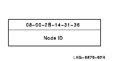
The network entity title (NET) is the same as the NSAP, with a selector field of 00. It identifies a node when the specific transport protocol to be used is either unknown or irrelevant. Figure 4-3 illustrates an NET.
Figure 4-3 Example NET

Area Address
An area address consists of the IDP, preDSP, and the local area fields of the NSAP. It identifies a level 2 routing area. Figure 4-4 illustrates an area address.
Figure 4-4 Example Area Address

Node ID
Consists of the node ID field of the NSAP. Identifies a particular node within a level 2 routing area.

Address Prefix
Consists of some leading portion of the NSAP, and can be of any length from zero digits up to the full length of the NSAP. Can be used in a reachable-address table to indicate that packets with a destination NSAP beginning with a specified address prefix are to be routed through a specified circuit.

Phase IV Prefix
Consists of all values up to (but not including) the local area field. Includes the AFI, IDI, and, if used, the preDSP. This value is used by DECnet-Plus when converting between Phase IV addresses and NSAPs.

If your network is to be interconnected with other networks, its NSAP must have a unique IDP and, possibly preDSP, to differentiate it from all other networks. For a unique IDP (and preDSP), you can contact an allocation authority, or you can create your own according to the guidelines in the following sections.
The following sections describe where to obtain an IDI (and preDSP) for
a specific AFI.
4.7.1 For a Private Network (AFI 49)
If your network will not be interconnected with other OSI networks, you
do not need a unique IDP. Use the AFI 49 with no IDI.
4.7.2 Allocation Authority for Single-Country Organizations (AFI 39)
The IDI value is assigned directly for each country by an authorized registration agent, according to ISO Standard 3166. The registration authority agent in the United States is the American National Standards Institute (ANSI), with offices in New York City.
In this case, the resulting IDP is entered as given by the allocation
authority. This IDP might also require the allocation of a value to be
placed in the preDSP.
4.7.3 Allocation Authority for International Organizations (AFI 47)
The IDI value is assigned directly for each international organization by an authorized registration agent, according to ISO Standard 6523-ICD.
In this case, the resulting IDP is entered as given by the allocation
authority. This IDP might also require the allocation of a value to be
placed in the preDSP.
4.7.4 Using an X.25 Data Network Address for the IDI (AFIs 37 and 53)
The IDI value is based on CCITT Recommendation X.121 and is created from a public or private data network address. The parts of this IDI are:
Company's subnetwork address prefix (DNIC and PNIC)   = 8107654
Address within company's subnetwork                   = 1234
Resulting IDP value = 37:81076541234:
4.7.5 Using a Telex Number for the IDI (AFIs 41 and 55)
The IDI value is based on CCITT Recommendation F.69 and is created from
a Telex number that has been assigned to your company or organization.
The parts of this IDI are:
Example:
Destination code (for Switzerland)  = 45
Local Telex number                  = 43 61 92
Resulting IDP value = 41:45436192:
4.7.6 Using a Telephone Number for the IDI (AFIs 43 and 57)
The IDI value is based on CCITT Recommendation E.163 and is created from a public switched telephone network (PSTN) number that has been assigned to your company or organization. The parts of this IDI are:
Consult your local PSTN for the world zone and the country numbers.
Choose one telephone number and use it to create a unique IDI value for your network. This number serves simply as a unique number that has been assigned to you.
Example:
World zone number (for U.S.A.)               = 1
Geographic area number (for Massachusetts)   = 508
Local number                                 = 555-1192
Resulting IDP value = 43:15085551192:
4.7.7 Using an ISDN Number for the IDI (AFIs 45 and 59)
The IDI value is based on CCITT Recommendation E.164 and is created from an integrated services digital network (ISDN) number that has been assigned to your organization. ISDN is a technology offered by the telephone carriers of the world that combines voice and digital network services in one media, allowing for digital data services through a single "wire." The standards that define ISDN are specified by CCITT.
The parts of this IDI are:
The NDC and SN, which together make up the national significant number, are administered within each country, usually by the PTT.
![[HR]](../../IMAGES/REDBAR.GIF)
  PLAN_PROFILE_005.HTML
  OSSG Documentation
   2-DEC-1996 12:32:10.86
Copyright © Digital Equipment Corporation 1996. All Rights Reserved.