![[Digital logo]](../../IMAGES/DIGITAL-LOGO.GIF)
![[HR]](../../IMAGES/REDBAR.GIF)
![[Digital logo]](../../IMAGES/DIGITAL-LOGO.GIF)
![[HR]](../../IMAGES/REDBAR.GIF)
3.2.4.2 Registering a System You Migrated from Phase IV to DECnet-Plus
Table 3-2 describes how you use decnet_register to
reregister a Phase IV system currently registered in the namespace
after migrating the system to DECnet-Plus.
| DECnet Phase V Name and Address | Autoregistration Allowed&185; | Autoregistration Disallowed&178; | ||
|---|---|---|---|---|
| Automatic Registration |
Manual Registration |
Automatic Registration |
Manual Registration |
|
|
Same Name
Same Address |
Yes | Not required | Yes | Not required |
|
Same Name
Different Address |
Yes | Not required | No | Before booting the system for the first time, reregister the system as a DECnet-Plus system. |
|
Different Name
Same Address |
Yes³ | Before booting the system for the first time, change the Phase IV name in the namespace to the new DECnet-Plus name. | No | Before booting the system for the first time, change the Phase IV name in the namespace to the new DECnet-Plus name. |
|
Different Name
Different Address |
Yes³ | Before booting the system for the first time, change the Phase IV name in the namespace to the new DECnet-Plus name. | No | Before booting the system for the first time, change the Phase IV name in the namespace to the new DECnet-Plus name and then reregister the system as a DECnet-Plus system. |
3.2.4.3 Registering a System You Changed from DECnet-Plus to Phase IV
Use decnet_register to reregister a system in the namespace
after changing the system from DECnet-Plus to Phase IV. Phase IV
systems cannot autoregister in the namespace. See your network
management book for further information.
3.2.5 Migrating OpenVMS Cluster Nodes (OpenVMS Only)
Before you start to transition any system in a OpenVMS cluster, you need to gather the following information:
Note
Do not enable the cluster alias on any DECnet-Plus OpenVMS cluster system until you have migrated all the systems participating in the alias.
To migrate an OpenVMS cluster node, when net$configure.com
prompts you for the system's node name and address, enter the system's
Phase IV node name and Phase IV address. For more information about
migrating OpenVMS cluster nodes to DECnet-Plus, refer to DECnet-Plus for OpenVMS Installation and Basic Configuration
or DECnet-Plus for OpenVMS Applications Installation and Advanced Configuration.
3.2.6 Migrating Local Area Networks
Migrating your LAN requires you to pay close attention to your routers. During Step 1 of your planning activities, you identified the routers in your network and specified their type, location, and function. Now you need that information.
This section shows the steps of a typical transition of a two-area LAN, highlighting:
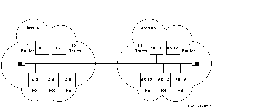
This section, without specific NCL commands, describes the LAN migration in a general way. See your router documentation for detailed instructions. Figure 3-1 shows an example of a LAN to be migrated to DECnet-Plus.
Figure 3-1 Two-Area Phase IV LAN to Be Migrated to DECnet-Plus
Begin the transition with the following steps:
Areas 4 and 55 are still separate and distinct. Phase V routers allow multiple areas to exist on a LAN if the areas have Phase IV-compatible addresses.
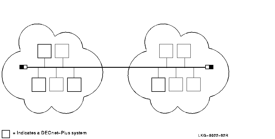
Figure 3-2 shows the LAN once transition has started.
Figure 3-2 Phase IV LAN with Some DECnet-Plus Systems
Note
Although each system has the same address it had as a Phase IV node, the addresses are never displayed (by NCL, for example) in the familiar Phase IV-style. In this LAN, the end system with the address 4.3 actually has the address 49::00-04:aa-00-04-00-03-10:20. DECnet-Plus automatically converts and stores the Phase IV address in this form.
The next step is to configure all level 1 routing in area 4 to link state as follows:
At this point, at level 1, area 4 is link state, and area 55 is routing vector. Level 2 in both areas is still routing vector.
Note
Changing the routing algorithm that each router runs does not affect the end systems. DECnet-Plus end nodes use the ES-IS protocol to communicate with Phase V routers, regardless of the routing algorithm the router is running.
Continue upgrading routers until both areas are running link state at level 1. This requires all routers to be upgraded to DECnet-Plus. Both areas are still using Phase IV-compatible addresses.
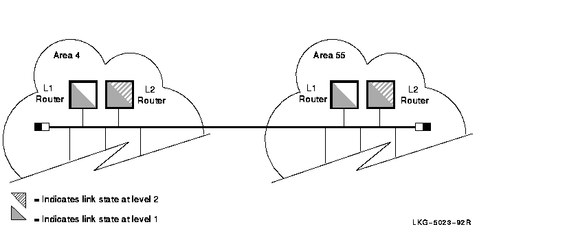
When all the level 2 routers in the LAN are running DECnet-Plus, you can convert the level 2 network to use link state simply by issuing a command to the router.
Figure 3-3 shows the network configuration.
Figure 3-3 LAN with Link State at Levels 1 and 2
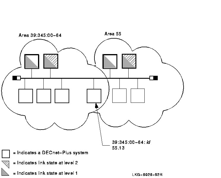
The next step is to move area 4 to DECnet Phase V addressing, which allows you to enable autoconfiguration and eventually remove area 4 from the network. The LAN can contain only one DECnet Phase V address area, as well as multiple Phase IV areas.
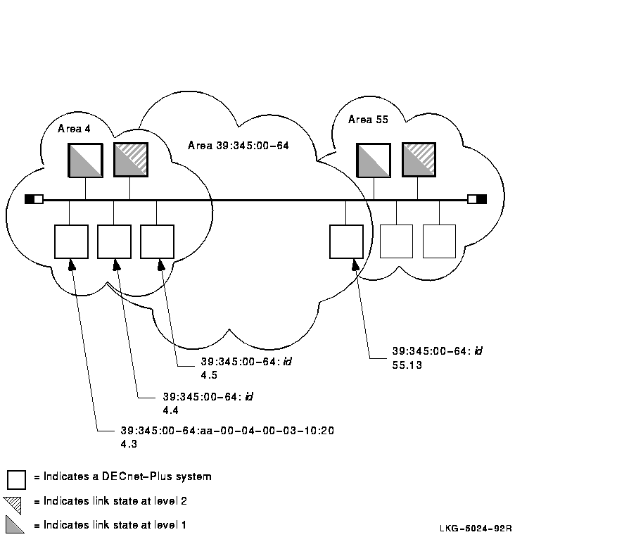
This example shows the creation of DECnet Phase V address area 100. In this example, the IDP is unique, with an AFI of 39 and an IDI of 345. The new DECnet Phase V area is 39:345:00-64. For instructions on how to construct your own unique IDP, see Chapter 4.
Follow these steps:
Immediately, each DECnet-Plus end system on the LAN (in both areas) autoconfigures to the new DECnet Phase V address. Each system also maintains its original manually-configured area 4 or 55 address. These systems are now multihomed (they have two distinct addresses). Thus, communication can reach the DECnet-Plus end systems in area 4 by the addresses 4.id or 39:345:00-64.id. The same is true for any DECnet-Plus end system in area 55. Figure 3-4 shows an example.
Figure 3-4 LAN with Multihomed Systems
Finally, when all Phase IV end systems in area 4 are either migrated to DECnet-Plus or moved to another area, you can remove area 4 from the network. Follow these steps:
The results of this last set of changes are that:
Figure 3-5 shows the next stage of the LAN configuration.
Figure 3-5 LAN with One DECnet Phase V Area
Eventually, the LAN manager finishes migrating the systems in area 55
to DECnet-Plus, so that area 55 can be removed from the LAN, thus
completing the transition to a DECnet-Plus LAN. For now, though, the
LAN can remain in the transition environment.
3.2.7 Configuring a DECnet-Plus End System in a Multivendor OSI Network
The DECnet-Plus software supports OSI addressing and OSI data-packet formats, allowing you to configure a DECnet-Plus end system as an OSI end system in a multivendor OSI environment. You can also configure other vendors' OSI end systems in a DECnet Phase V network (see your network management guide).
To configure a DECnet-Plus end system to operate in a multivendor OSI network, install the DECnet-Plus software and configure the system as follows:
3.3 Additional Tasks
You have several additional transition tasks. Some are performed
automatically, and others you perform, perhaps on an on-going basis, as
your network operation requires:

Session Control maintains a database of applications that is similar to the Phase IV object database. This application database includes information about DECnet utilities, such as FAL (file access listener) or dlogin, and user-written application entities that are registered using NCL commands. The applications list is used to associate incoming connect requests with the relevant processes to handle them. If a Phase IV application uses the object spawner to start up a target application, you must convert the object database to an application database for the program to function properly.
The objtoncl utility allows you to convert your Phase IV object databases to DECnet-Plus application databases. This utility generates the appropriate NCL commands needed to make the conversion. You can use this utility to convert all the objects in a volatile database, all the objects in a permanent database, or selected objects in either type of database.
The objtoncl utility uses the following syntax:
/usr/field/objtoncl[-v] [-p] [-f] [filename] [object name]
The switches allow you to specify which object database to convert. The object name allows you to specify a particular object in a given database. Table 3-3 explains each switch.
| Switch | Meaning |
|---|---|
| -v | Specifies conversion of the objects in the volatile database in /usr/lib/dnet/objects_v. |
| -p | Specifies conversion of the objects in the permanent databases in /usr/lib/dnet/objects_p. This switch does not have to be specified explicitly because it is the default. |
| -f | Allows you to specify a particular object database file name. |
If you only want to convert specific objects, you can specify them as part of the command line argument. For example, the following arguments specify the conversion of specific objects in a specific database file:
objtoncl -f objects.saved myobj yourobj hisobj herobj
You can redirect the output of the command line to a file. You can then
modify the NCL commands before inputting the file into NCL.
3.3.2 Converting the Phase IV Proxy File (Digital UNIX Only)
Phase IV nodes use a proxy file, /etc/dnet_proxy, to specify proxy access. DECnet-Plus systems use a proxy database managed by NCL instead. When you upgrade your Phase IV node to DECnet-Plus, if you want to maintain the same proxy access, you can also upgrade the Phase IV proxy file to a DECnet-Plus proxy database.
DECnet-Plus provides a transition tool, /usr/field/proxytoncl, that generates the NCL commands necessary to create proxy entries in the DECnet-Plus proxy database. These proxy entries are equivalent to the entries in the original Phase IV proxy file.
Note
Check the entries in the Phase IV proxy file for wildcards:
- You can use wildcards to specify user names (node::*). The resulting NCL commands create proxy access for all users on the specified node.
- You cannot use wildcards to specify node names (*::* or *::user_name). The resulting NCL commands create proxy access on the node with the name "*".
To generate the NCL commands, issue the following command as superuser:
# /usr/field/proxytoncl
The command displays the NCL commands to standard output. You can redirect the NCL commands to a file and modify them before inputting the file to NCL. Two reasons to modify the resulting NCL commands before using them are:
If your DECnet-Plus system will be a remote installation service (RIS) server or Digital UNIX load host, you need to create the new MOP client database required by the MOP Version 4 protocol. You create this database using /usr/field/update_mopdb, which converts the Phase IV MOP database, /usr/lib/dnet/nodes_p, to the new DECnet-Plus MOP client database, /var/dna/mop_client_db.
During installation, if you have a nodes_p and no existing MOP client database on your system, decnetsetup automatically runs the MOP database conversion tool and creates a new MOP client database for you.
If decnetsetup did not create a database for your system, you can create one manually using the /usr/field/update_mopdb tool, as follows:
After completing these steps, your system is ready to function as an
RIS server or an Digital UNIX load host.
3.3.4 Becoming Familiar with NCL Commands, Network Management Modules, and Network Management Tasks
Use NCL to manage DECnet-Plus software by specifying entity values. You can use NCL commands to:
NCL also provides module-specific functions, for example, loopback testing within the Modem Connect module.
In addition to its entity-related functions, NCL provides control functions such as:
Table 3-4 lists some network management tasks and the related network management entities that you set or modify using NCL commands to perform these tasks. You can use this table during transition to help you learn the modules and entities associated with specific network management tasks. (A complete version of this table also appears in your network management guide.)
Note
All required modules are enabled and all required entities are set during initial configurations, either automatically or by you. Use interactive NCL commands to change initial settings.
Some management tasks related to the transition are required only if your network operations need them:
In DECnet-Plus, the Transport layer segments and reassembles user messages to a size acceptable to the Routing layer on that system. This method differs from the Phase IV method, in which the Transport layer segments and reassembles user messages to a size appropriate to the complete path over which packets must pass.
![[HR]](../../IMAGES/REDBAR.GIF)
  PLAN_PROFILE_004.HTML
  OSSG Documentation
   2-DEC-1996 12:32:09.20
Copyright © Digital Equipment Corporation 1996. All Rights Reserved.