![[Digital logo]](../../IMAGES/DIGITAL-LOGO.GIF)
![[HR]](../../IMAGES/REDBAR.GIF)
![[Digital logo]](../../IMAGES/DIGITAL-LOGO.GIF)
![[HR]](../../IMAGES/REDBAR.GIF)
2.1 Step 1: Document the Current Network Configuration
Planning the migration of a network requires an accurate, up-to-date
picture of the network's current state. This picture should be a
detailed topological map of the network. Use the information you gather
in developing this map as input for decisions you make in the following
steps.
For example, information on products that cannot make the transition to DECnet-Plus can help determine the configuration of end systems and routers. Identifying all the routers in your network, and determining each one's type, helps you in Step 2 to decide which routing algorithm to use for each Phase V router. Therefore, the more complete your topological map, the more informed your decisions can be.
The decnet_migrate tool provides two commands that, when used together, create a report on the network's configuration:
| COLLECT | Collects specified information from specified nodes |
| REPORT | Creates a report from the data gathered by COLLECT |
The tool offers another command, SHOW PATH, that displays the possible paths that node-to-node communication might take through the network, helping to determine what effect the transition has had on the network's communication paths. For complete information about using decnet_migrate, see your network management manual.
To complete Step 1:
DECnet-Plus offers various transition strategies to suit individual customer networks. Most strategies can be divided into two categories, based on your answer to the following question: Does the network need DECnet Phase V areas?
Your network needs DECnet Phase V areas if:
Your network needs to maintain Phase IV areas if:
If your network needs Phase IV addressing, your general strategy will be to move the network partially to a DECnet-Plus environment, at least for the near future. You will have a configuration with both Phase IV areas and DECnet Phase V areas.
If your network is ready to use OSI addresses that are beyond the
limits of Phase IV and, therefore, not compatible with Phase IV
addresses, your strategy will be to move the network entirely to the
DECnet-Plus environment with no Phase IV areas and no Phase IV nodes.
2.2.1 If the Network Is Not Moving Entirely to the DECnet-Plus Environment
If the network needs to remain in a DECnet Phase IV environment for at least one area, an appropriate transition strategy might be that the network has DECnet-Plus systems with Phase IV-compatible addresses. These systems will be able to communicate with the remaining Phase IV nodes.
Another option is that you decide to gain experience using DECnet-Plus in one part of your network before migrating the entire network to DECnet-Plus. You can migrate one area to the DECnet-Plus environment, while the network as a whole operates in the transition environment.
In addition, as part of your "partial" transition strategy, you can use the Local namespace to maintain DECnet-Plus node-name and OSI addressing information until it is more convenient to design and move to a distributed namespace.
Install DECnet-Plus software onto each system that is ready to migrate
and assign it a Phase IV-compatible address during the configuration
procedure. The network transition plan, then, would highlight the order
of migration for individual nodes.
2.2.2 If the Network Is Moving Entirely to the DECnet-Plus Environment
If you need at least one DECnet Phase V area, determine whether or not
the entire network can move to DECnet-Plus. For example, consider a
small, single-area LAN of approximately 20 nodes. If it has no Phase
III nodes or other products that cannot migrate, you can migrate it
entirely to a DECnet-Plus environment by installing DECnet-Plus
software on every end system.
2.3 Step 3: Develop a New Network Configuration
To develop a network configuration, make the following decisions:
Your planning activities include:
As you create your new network configuration, review the information in Chapter 1 for:
In addition, to determine the configuration of end systems and routers, use the following information to guide your decisions:
In the Phase IV environment, LANs can have multiple areas. In the DECnet-Plus environment, however, a LAN can have only one DECnet Phase V area address: an area over 63. This area can have a virtually limitless number of systems, but they all must reside in that single DECnet Phase V area address space. In the transition environment, you can give a LAN multiple areas if the area numbers are within Phase IV limits: 63 or less.
If you plan to migrate a multiple Phase IV-area LAN to the DECnet-Plus
environment, during the migration, the DECnet-Plus end systems will be
multihomed to a Phase IV-compatible area as well as to an area in the
larger DECnet Phase V address space.
2.3.1.2 End-System-Only LAN Configurations
A LAN can consist of end systems only. A DECnet-Plus LAN without routers has virtually no limit on the number of systems it can contain.
The end system to intermediate system (ES-IS) routing exchange protocol (ISO 9542) provides the process by which end nodes communicate with routers, or with each other, to exchange configuration information. In a DECnet-Plus end-system-only network, end systems on a LAN use the ES-IS protocol to communicate directly with each other without depending on a router.
DECnet-Plus end systems communicate directly by using a multicast address called "All End Systems." All end systems normally listen to this address for Router Hello messages, identifying routers to end systems. An end system also uses this multicast address when sending a packet to an end system for which it does not have a cache entry.
When an end system receives a multicast data packet that belongs to itself, it makes a cache entry for the sending end system and sends back an End System Hello, which causes the other end system to make an entry in its cache. When it has another packet to send, the end system checks its cache and uses the cached address instead of the multicast address.
In a LAN with only end systems, these systems can have Phase IV-compatible addresses, extended DECnet Phase V addresses, or a mixture of both. You can allow end systems to autoconfigure their OSI addresses, or you can manually assign them Phase IV-compatible addresses.
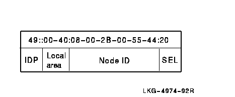
When end systems do not have an assigned Phase IV address, they construct an NSAP for each transport operating over routing. Each NSAP is constructed by concatenating the default local area address (49::00-40), the node ID, and the selector representing the transport (NSP or OSI transport). The Figure 2-1 illustrates a network address, or NSAP, of an autoconfigured end system in an end-system-only network:
Figure 2-1 Autoconfigured End System NSAP

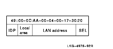
When an end system does have an assigned Phase IV address, it constructs an NSAP for each transport operating over routing by concatenating the local AFI (49), 2 octets containing the area portion of the Phase IV address, a Phase IV-style LAN address (aa-00-04-00-xx-xx), and the selector representing the transport. Figure 2-2 illustrates this type of NSAP.
Figure 2-2 Assigned Phase IV Address NSAP

The corresponding Phase IV address is 12.23.
Instead of allowing an end system to autoconfigure its address, you can
assign it an OSI address. To manually configure, use the DECnet-Plus
configuration utility, net$configure.com (for OpenVMS) or
decnetsetup (for Digital UNIX), or use NCL. For details, see
your network management guide.
2.3.1.3 Multicircuit End-System Configurations
A Phase IV end node can have multiple circuits to one or several adjacent nodes, but only one of these circuits can be active at a time. Among Phase IV nodes, only routers have multiple active circuits. DECnet-Plus end systems, on the other hand, can be multicircuited. DECnet-Plus multicircuit end systems can have up to four multiple active circuits to either the same or different subnetworks.
A subnetwork is a communications network, within a group of interconnected networks, of OSI systems that use a common addressing format and that forms an autonomous whole. Examples are
X.25 packet switched networks, HDLC data links and ISO 8802.3 LANs.
These restrictions apply to multicircuit configurations:
Multicircuit end systems do not forward packets to other systems. However, the Routing layer of a DECnet-Plus end system receives information from routers about paths to destinations. The end system gets this information by using the ES-IS protocol to communicate with routers in its area. The routers give the end system information about direct paths to destinations, that is, paths that do not require forwarding the packet. The end system stores the information in a cache and uses it to select an appropriate circuit for sending data to a particular destination. If an end system has no information about a certain destination, it selects a router at random and forwards the data to that router.
Use the following guidelines when you configure multicircuit end systems:
DECnet-Plus for OpenVMS and DECnet/OSI for Digital UNIX end systems with multiple active circuits provide redundancy and increased data throughput. An end system with multiple circuits to an Ethernet LAN, for example, provides a guarantee that if one circuit fails, this system still has access to the LAN. There is no gain in data throughput, however, since both circuits go to the same LAN.
You can also configure a multiple-active-circuit end system with its circuits to different LANs. Figure 2-3 shows an end system with circuits to two different Ethernet LANs. This configuration is useful where reliability is critical such as in a network that supports banking applications, for example. This configuration also provides for increased data throughput, since circuits to two different LANs can carry double the number of packets.
Figure 2-3 Multicircuit End System with Circuits to Two Ethernet LANs


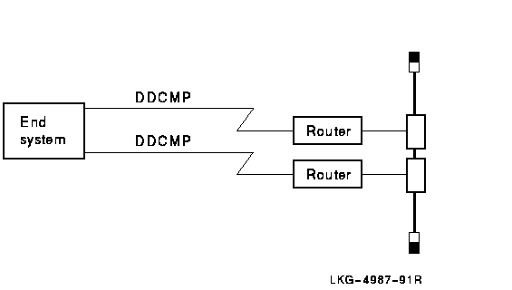
Figure 2-4 shows a configuration in which an end system has two active Digital Data Communications Message Protocol (DDCMP) circuits to different routers on a LAN. This configuration could provide redundancy in a situation where, for example, there is concern about disturbances on one of the telephone lines.<>
Figure 2-4 Multicircuit End System with Two DDCMP Circuits

Though you can configure circuits to either the same or a different subnetwork, you can enable the Phase IV address of only one circuit per LAN. To configure a multicircuit end system with a Phase IV address and one or more circuits to the same LAN, take the following steps:
ncl> set routing circuit csmacd-1 enable phase iv address=false
You can set the Routing characteristic enable phase IV address in two ways:
DECnet-Plus software allows OSI-compliant systems from other vendors to participate as end systems in the DECnet Phase V network. Use the following guidelines when you add other vendors' OSI-compliant systems to your network:
DECnet-Plus provides support for the inactive Network layer protocol specified in ISO 8473. The inactive subset bypasses the Network layer, running transport directly over a data link connected to a LAN. You can use this configuration when the source and destination end systems are on the same LAN.
Consider these guidelines before using the inactive Network layer protocol:
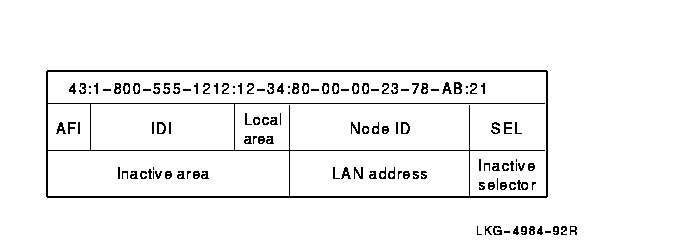
To configure the inactive subset on a circuit, use NCL to set the circuit attribute inactive area address. The area address portion of the NSAP address is placed in this set, as shown in Figure 2-5.
Figure 2-5 Area Address Portion of the NSAP Address

This command configures the inactive subset on circuit-1:
ncl> set routing circuit circuit-1 inactive area address {49::ff-00}
You can assign only one inactive area address to a circuit.
During transmission, when a service data unit (SDU) is passed to an end system's Network layer, transport provides a destination NSAP. If the area address portion of the destination NSAP matches the inactive area address assigned to the circuit, then routing uses the inactive Network layer protocol and passes the SDU directly to the Data Link layer, specifying the ID portion of the destination NSAP as the destination data link address.
If an end system's Network layer receives a protocol data unit (PDU) with the inactive Network layer protocol header on a circuit that has the inactive area address set, then routing passes the SDU up to transport.
In addition, routing calculates the source and destination NSAPs as follows:
Figure 2-6 Source NSAP

If an end system's Network layer receives a PDU with an inactive
Network layer protocol header on a circuit that does not have the
inactive area address set, then the PDU is dropped.
2.3.4 Planning Addressing
When planning your network's addressing scheme, determine the need for
unique IDP and DECnet Phase V addresses, which, in turn, depends on the
general transition strategy you chose in Step 2.
2.3.4.1 Do You Need a Unique IDP for Your Network?
DECnet-Plus software includes a default IDP, which has the local AFI of 49 and a null IDI. The local AFI and null IDI means that the IDP is intended for use within a private network. Therefore, the local AFI is useful only in a network not connected to any external networks.
As network manager, consider whether the default IDP is sufficient for your network. If you plan to connect your network to other networks, you must obtain a unique IDP. Consider obtaining a unique IDP if there is a possibility that, in the future, you might connect your network to other networks. Otherwise, the default IDP is sufficient.
For information about obtaining a unique IDP for your network, see
Section 4.7. If you change your network's IDP, use the
decnet_register tool (see your network management guide).
2.3.4.2 Do You Need Extended OSI Addresses?
The general transition strategy you planned in Step 2 determines your decision about the need for OSI addressing that goes beyond Phase IV address limitations:
A network with one or more DECnet Phase V areas requires well-planned addresses because:
Also use the following guidelines when planning addresses:
When you plan routing configurations, use the following guidelines:
ncl> set node .ultra.router routing manual L1 algorithm link state algorithm
![[HR]](../../IMAGES/REDBAR.GIF)
  PLAN_PROFILE_002.HTML
  OSSG Documentation
   2-DEC-1996 12:32:05.79
Copyright © Digital Equipment Corporation 1996. All Rights Reserved.