![[HR]](../../IMAGES/REDBAR.GIF)
This appendix contains information about MEMORY CHANNEL, a new, high-performance cluster interconnect technology. MEMORY CHANNEL becomes available with OpenVMS Alpha Version 7.1, and supports several configurations.
This chapter contains the following sections:
| Section | Content |
|---|---|
| Product Overview | High-level introduction to the MEMORY CHANNEL product and its benefits, hardware components, and configurations. |
| Technical Overview | More in-depth technical information about how MEMORY CHANNEL works. |
MEMORY CHANNEL is a new, high-performance cluster interconnect technology for PCI-based Alpha systems. With the benefits of very low latency, high bandwidth, and direct memory access, MEMORY CHANNEL complements and extends the unique ability of an OpenVMS Cluster to work as a single, virtual system.
MEMORY CHANNEL offloads internode cluster traffic (such as lock management communication) from existing interconnects---CI, DSSI, FDDI, and Ethernet---so that they can process storage and network traffic more effectively. MEMORY CHANNEL significantly increases throughput and decreases the latency associated with traditional I/O processing.
Any application that must move large amounts of data among nodes will
benefit from MEMORY CHANNEL. It is an optimal solution for applications
that need to pass data quickly, such as real-time and transaction
processing. MEMORY CHANNEL also improves throughput in high-performance
databases and other applications that generate heavy OpenVMS Lock
Manager traffic.
B.1.1 MEMORY CHANNEL Features
MEMORY CHANNEL technology provides the following features:
A MEMORY CHANNEL cluster is joined together by a hub, a desktop-PC sized unit which provides a connection among systems. The hub is connected to a system's PCI adapter by a link cable. Figure B-1 shows all three hardware components required by a node to support MEMORY CHANNEL:
Figure B-1 MEMORY CHANNEL Hardware Components
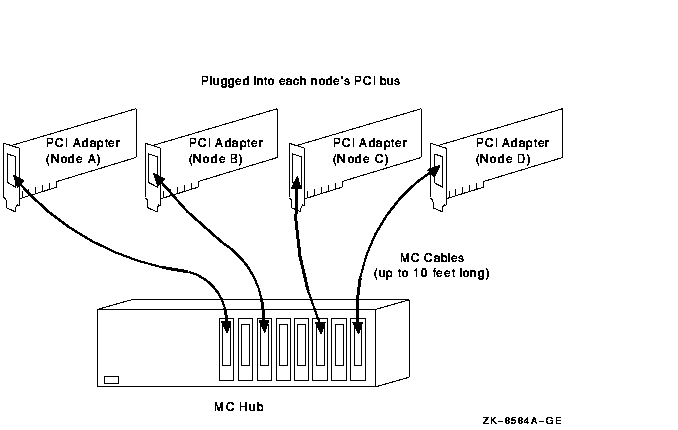
The PCI adapter pictured in Figure B-1 has memory mapping logic that enables each system to communicate with the others in the MEMORY CHANNEL cluster.
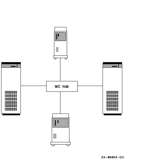
Figure B-2 shows an example of four-node MEMORY CHANNEL cluster with a hub at its center.
Figure B-2 Four-Node MEMORY CHANNEL Cluster
A MEMORY CHANNEL hub is not required in clusters that contain only two nodes. In a two-node configuration like the one shown Figure B-3, the same adapters and cable are used, and one of the PCI adapters serves as a virtual hub. You can continue to use the adapters and cable if you expand to a larger configuration later.
Figure B-3 Virtual Hub MEMORY CHANNEL Cluster

Because MEMORY CHANNEL supports a distance of 3 m (10 ft) between nodes, it is typically configured in adjacent racks of servers.
Figure B-4 shows a basic MEMORY CHANNEL cluster that uses the SCSI interconnect for storage. This configuration achieves two advantages: performance on the MEMORY CHANNEL interconnect and low cost on the SCSI interconnect.
Figure B-4 MEMORY CHANNEL- and SCSI-Based Cluster

In a configuration like the one shown in Figure B-4, the MEMORY CHANNEL interconnect handles internode communication while the SCSI bus handles storage communication.
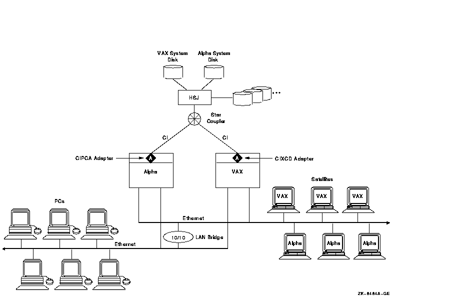
You can integrate MEMORY CHANNEL with your current systems. Figure B-5 shows an example of how to add MEMORY CHANNEL to a mixed-architecture CI- and SCSI-based cluster. In this example, the BI- and XMI-based VAX systems are joined in the same CI cluster with the PCI-based Alpha MEMORY CHANNEL systems.
Figure B-5 MEMORY CHANNEL CI- and SCSI-Based Cluster
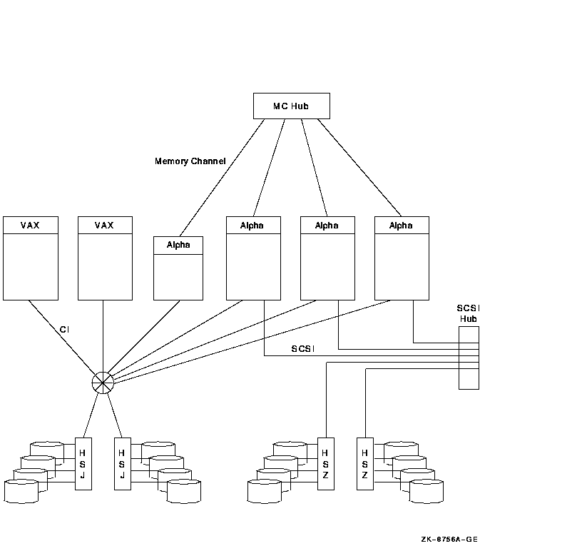
Because the MEMORY CHANNEL interconnect is not used for storage and booting, you must provide access to a boot device through one of the other interconnects. To use Figure B-5 as an example, one of the CI-based disks would be a good choice for a boot device because all nodes have direct access to it over the CI.
MEMORY CHANNEL can also be integrated into an existing DSSI cluster, as shown in Figure B-6.
Figure B-6 MEMORY CHANNEL DSSI-Based Cluster
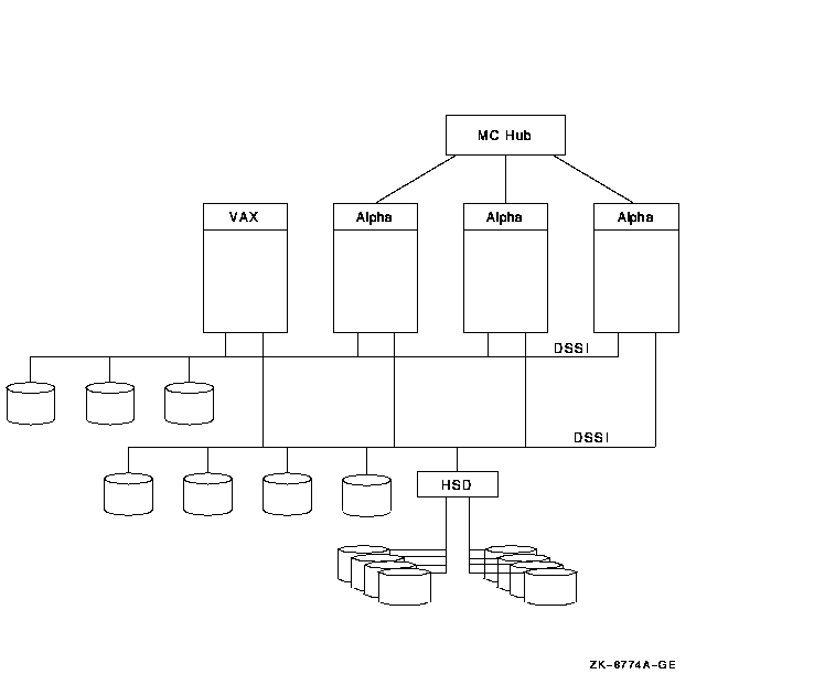
As Figure B-6 shows, the three MEMORY CHANNEL systems and the VAX
system have access to the storage that is directly connected to the
DSSI interconnect as well as to the SCSI storage attached to the HSD
controller. In this configuration, MEMORY CHANNEL handles the Alpha
internode traffic, while the DSSI handles the storage traffic.
B.1.3.1 Configuration Requirements
For its initial release in OpenVMS Version 7.1, MEMORY CHANNEL supports the platforms and configurations shown in Table B-1.
| Requirement | Description |
|---|---|
| Configuration |
In OpenVMS Alpha Version 7.1, MEMORY CHANNEL supports the following
configuration requirements:
|
| Host systems |
MEMORY CHANNEL supports the following systems:
|
This section describes in more technical detail how MEMORY CHANNEL
works.
B.2.1 Comparison With Traditional Networks and SMP
You can think of MEMORY CHANNEL as a form of "stretched SMP bus" that supports enough physical distance to interconnect 2 to 4 (and in the future, 8) systems. However, MEMORY CHANNEL differs from an SMP environment where multiple CPUs can directly access the same physical memory. MEMORY CHANNEL requires each node to maintain its own physical memory, even though the nodes share MEMORY CHANNEL global address space.
MEMORY CHANNEL fills a price/performance gap between the high performance of SMP systems and traditional packet-based networks. Table B-2 shows a comparison among the characteristics of SMP, MEMORY CHANNEL, and standard networks.
| Characteristics | SMP | MEMORY CHANNEL | Standard Networking |
|---|---|---|---|
| Bandwidth (MB/s) | 1000+ | 100+ | 10+ |
| Latency (ms/simplest message) | 0.5 | Less than 5 | About 300 |
| Overhead (ms/simplest message) | 0.5 | Less than 5 | About 250 |
| Hardware communication model | Shared memory | Memory-mapped | Message passing |
| Hardware communication primitive | Store to memory | Store to memory | Network packet |
| Hardware support for broadcast | n/a | Yes | Sometimes |
| Hardware support for synchronizaton | Yes | Yes | No |
| Hardware support for node hot swap | No | Yes | Yes |
| Software communication model | Shared memory | Fast messages, shared memory | Messages |
| Communication model for errors | Not recoverable | Recoverable | Recoverable |
| Supports direct user mode communication | Yes | Yes | No |
| Typical physical interconnect technology | Backplane etch | Parallel copper cables | Serial fiber optics |
| Physical interconnect error rate |
Extremely low
order: less than one per year |
Extremely low
order: less than one per year |
Low order:
several per day |
| Hardware interconnect method | Special purpose connector and logic | Standard I/O bus adapter (PCI) | Standard I/O bus adapter (PCI and others) |
| Distance between nodes (m) | 0.3 | 6 in a hub configuration and 3 in a two-node configuration | 50--1000 |
| Number of nodes | 1 | 8 | Hundreds |
| Number of processors | 6--12 | 8 times the maximum number of CPUs in an SMP system | Thousands |
| Failure model | Fail together | Fail separately | Fail separately |
B.2.2 MEMORY CHANNEL in the OpenVMS Cluster Architecture
As Figure B-7 shows, MEMORY CHANNEL functionality has been
implemented in the OpenVMS Cluster architecture just below the System
Communication Services layer. This design ensures that no changes are
required to existing applications because higher layers of OpenVMS
Cluster software are unchanged.
Figure B-7 OpenVMS Cluster Architecture and MEMORY CHANNEL
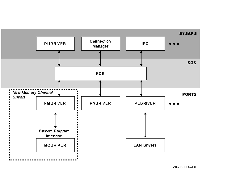
MEMORY CHANNEL software consists of two new drivers:
| Driver | Description |
|---|---|
| PMDRIVER | Emulates a cluster port driver. |
| MCDRIVER | Provides MEMORY CHANNEL services and an interface to MEMORY CHANNEL hardware. |
In a MEMORY CHANNEL configuration, a section of system physical address space is shared among all nodes. When a system writes data to this address space, the MEMORY CHANNEL hardware also performs a global write so that this data is stored in the memories of other systems. In other words, when a node's CPU writes data to the PCI address space occupied by the MEMORY CHANNEL adapter, the data is sent across the MEMORY CHANNEL interconnect to the other nodes. The other nodes' PCI adapters map this data into their own memory. This infrastructure enables a write to an I/O address on one system to get mapped to a physical address on the other system. The next two figures explain this in more detail.
Figure B-8 shows how MEMORY CHANNEL global address space is addressed in physical memory.
Figure B-8 Physical Memory and I/O Address Space
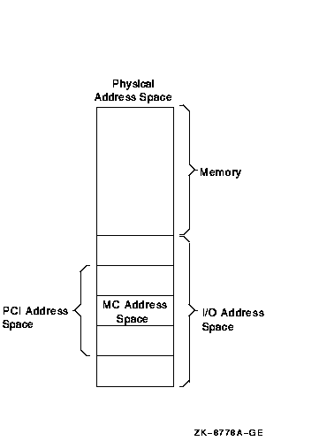
Figure B-8 shows the typical address space of a system, divided into physical memory and I/O address space. Within the PCI I/O address space, MEMORY CHANNEL consumes 128 to 512 MB of address space. Therefore, the MEMORY CHANNEL PCI adapter can be addressed within this space, and the CPU can write data to it.
Every system in a MEMORY CHANNEL cluster allocates this address space for MEMORY CHANNEL data and communication. By using this address space, a CPU can perform global writes to the memories of other nodes.
To explain global writes more fully, Figure B-9 shows the internal bus architecture of two nodes, node A and node B.
Figure B-9 MEMORY CHANNEL Bus Architecture
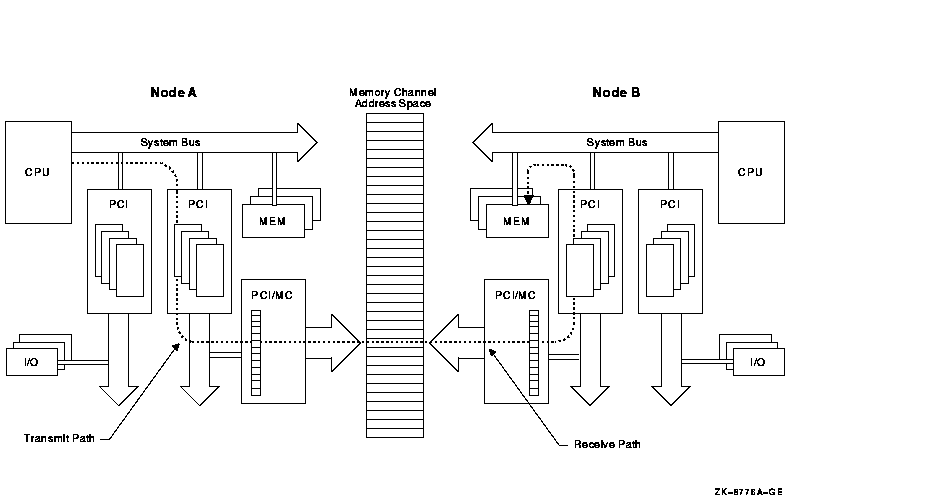
In the example shown in Figure B-9, node A is performing a global write to node B's memory, in the following sequence:
If all nodes in the cluster agree to address MEMORY CHANNEL global address space in the same way, they can virtually "share" the same address space and the same data. This is why MEMORY CHANNEL address space is depicted as a common, central address space in Figure B-9.
MEMORY CHANNEL global address space is divided into pages of 8 KB (8,192 bytes). These are called MC pages. These 8 KB pages can be mapped similarly among systems.
The "shared" aspect of MEMORY CHANNEL global address space is set up using the page control table, or PCT, in the PCI adapter. The PCT has attributes that can be set for each MC page. Table B-3 explains these attributes.
| Attribute | Description |
|---|---|
| Broadcast | Data is sent to all systems or, with a node ID, data is sent to only the specified system. |
| Loopback | Data that is sent to the other nodes in a cluster is also written to memory by the PCI adapter in the transmitting node. This provides message order guarantees and a greater ability to detect errors. |
| Interrupt | Specifies that if a location is written in this MC page, it generates an interrupt to the CPU. This can be used for notifying other nodes. |
| Suppress transmit/receive after error | Specifies that if an error occurs on this page, transmit and receive operations are not allowed until the error condition is cleared. |
| ACK | A write to a page causes each receiving system's adapter to respond with an ACK (acknowledge), ensuring that a write (or other operation) has occurred on remote nodes without interrupting their hosts. This is used for error checking and error recovery. |
MEMORY CHANNEL software comes bundled with the OpenVMS Cluster software. After setting up the hardware as described in this chapter, implementation of MEMORY CHANNEL takes place by answering prompts in CLUSTER_CONFIG.COM (or CLUSTER_CONFIG_LAN.COM), including one specific to MEMORY CHANNEL. The prompt asks if you want to enable MEMORY CHANNEL for node-to-node communications for the local computer. By responding "Yes", MC_SERVICES_P2, the system parameter that controls whether MEMORY CHANNEL is in effect, is set to 1. This setting causes the driver, PMDRIVER, to be loaded and the default values for the other MEMORY CHANNEL system parameters to take effect.
For guidelines for using the other MEMORY CHANNEL system parameters, see the OpenVMS Version 7.1 Release Notes.
For more detailed information about setting up the MEMORY CHANNEL hub, link cables, and PCI adapters, see the MEMORY CHANNEL User's Guide, order number EK-PCIRM-UG.
This chapter describes the CI-to-PCI adapter (CIPCA) that is supported in OpenVMS Alpha Versions 6.2--1H2, 6.2--1H3, and 7.1. CIPCA is not supported in OpenVMS Version 7.0 The CIPCA adapter supports specific Alpha servers and OpenVMS Cluster configurations.
This chapter contains the following sections:
| Section | Content |
|---|---|
| CIPCA Overview | High-level introduction to the CIPCA and its benefits, as well as examples of two configurations that use the CIPCA. |
| Technical Specifications | Information about the CIPCA's performance metrics and configuration requirements. |
With the release of OpenVMS Alpha Version 6.2--1H2, Digital introduced a CI-to-PCI adapter (CIPCA).
With the CIPCA, Alpha servers that contain a combination of the PCI and the EISA buses can now connect to the CI.
CIPCA support for Alpha servers provides the following features and benefits to customers:
| Feature | Benefit |
|---|---|
| Lower entry cost and more configuration choices | If you require midrange compute power for your business needs, CIPCA enables you to integrate midrange Alpha servers into your existing CI cluster. |
| High-end Alpha speed and power | If you require maximum compute power, you can use the CIPCA with both the AlphaServer 8200 systems and AlphaServer 8400 systems that have PCI and EISA I/O subsystems. |
| Cost-effective Alpha migration path | If you want to add Alpha servers to an existing CI VAXcluster, CIPCA provides a cost-effective way to start migrating to a mixed-architecture cluster in the price/performance range that you need. |
| Advantages of the CI |
The CIPCA connects to the CI, which offers the following advantages:
|
Figure C-1 shows an example of a mixed-architecture CI OpenVMS Cluster that has two servers: an Alpha and a VAX.
Figure C-1 CIPCA in a Mixed-Architecture OpenVMS Cluster
As Figure C-1 shows, you can use the CIPCA adapter to connect an Alpha server to a CI OpenVMS Cluster that contains a VAX server with a CIXCD (or CIBCA-B) adapter. This enables you to smoothly integrate an Alpha server into a cluster that previously comprised only high-end VAX systems.
Figure C-2 shows another example of a configuration that uses the CIPCA to connect systems with the CI. In this example, each Alpha has two CIPCA adapters that ensure redundant paths to all of the storage in the OpenVMS Cluster. Also, the Alpha systems are connected to a high-speed FDDI interconnect that provides additional connectivity for PC clients and OpenVMS satellites.
Figure C-2 CIPCA in an Alpha OpenVMS Cluster
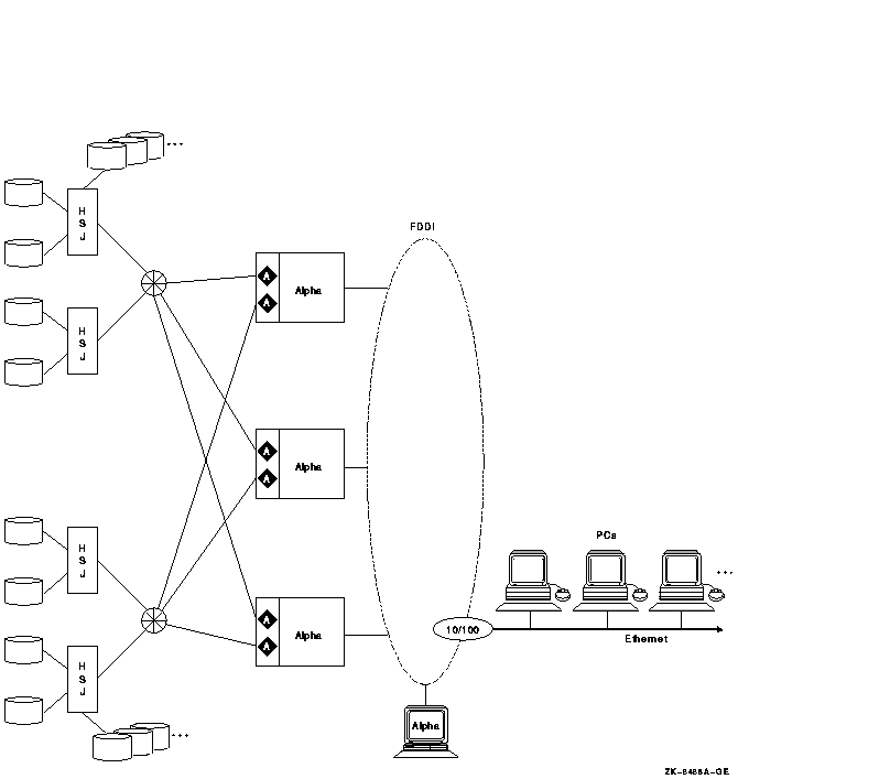
Figure C-1 and Figure C-2 show that the CIPCA makes the performance, availability, and large storage access of the CI available to a wide variety of users. The CI has a high maximum throughput. Both the PCI-based CIPCA and the XMI based CIXCD are highly intelligent microprocessor-controlled adapters that consume minimal CPU overhead.
Because the effective throughput of the CI bus is high, the CI interconnect is not likely to be a bottleneck. In large configurations like the one shown in Figure C-2, multiple adapters and CI connections provide excellent availability and throughput.
Although not shown in Figure C-1 and Figure C-2, you can increase
availablity by placing disks on a SCSI interconnect between a pair of
HSJ controllers and connecting each HSJ to the CI.
C.2 Technical Specifications
The CIPCA is a two-slot optional adapter that requires one PCI slot and one EISA slot on the host computer. The EISA slot supplies only power (not bus signals) to the CIPCA. CIPCA's driver, PCAdriver, was first made available with OpenVMS Alpha Version 6.2--1H2 and is included in Version 6.2--1H3 and OpenVMS Alpha Version 7.1. Table C-1 shows the performance of the CIPCA in relation to the CIXCD adapter.
| Performance Metric | CIPCA | CIXCD |
|---|---|---|
| Read request rate (I/Os) | 4900 | 5500 |
| Read data Rate (MB/s) | 10.6 | 10.5 |
| Write request rate (I/Os) | 4900 | 4500 |
| Write data rate (MB/s) | 9.8 | 5.8 |
| Mixed request rate (I/Os) | 4800 | 5400 |
| Mixed data rate (MB/s) | 10.8 | 9.2 |
C.2.1 Configuration Requirements
Following are the configuration requirements for the CIPCA:
CLI> SET THIS CI_ARB = SYNC
  6318P013.HTM
  OSSG Documentation
  26-NOV-1996 11:20:32.97
Copyright © Digital Equipment Corporation 1996. All Rights Reserved.