![[Digital logo]](../../IMAGES/DIGITAL-LOGO.GIF)
![[HR]](../../IMAGES/REDBAR.GIF)
![[Digital logo]](../../IMAGES/DIGITAL-LOGO.GIF)
![[HR]](../../IMAGES/REDBAR.GIF)
When the packets reach their destination, they are reassembled so that the original order of the packets in the data message is maintained.
Figure 4-2 Packets Traveling Over a PSDN
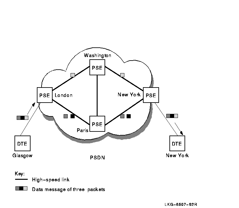
There are two types of data terminal equipment:
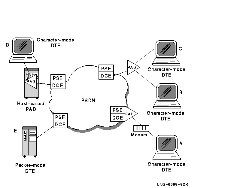
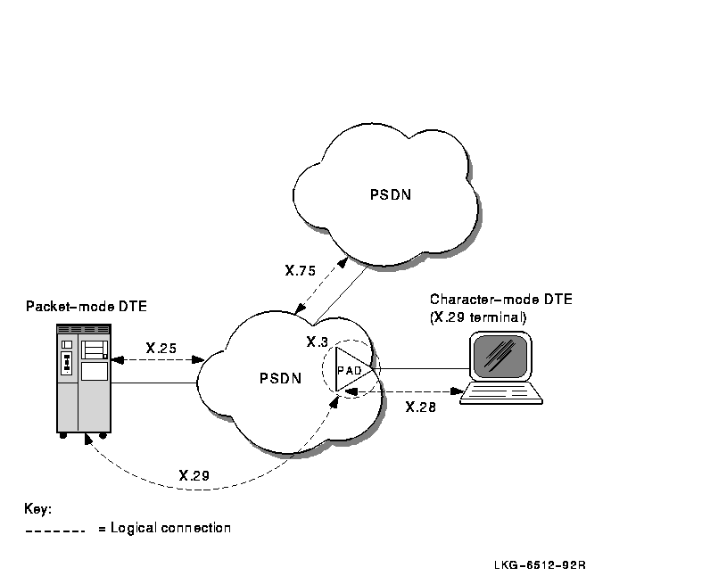
PADs allow character-mode DTEs to access PSDNs. A PAD performs the following functions:
Figure 4-3 shows the following PADs:
Figure 4-3 Connecting Character-Mode DTEs to a PSDN
A protocol is a set of rules for the formatting and sequencing of data. X.25 describes three protocol levels for the interface between a DTE and a DCE:
Figure 4-4 shows the three protocol levels.
Figure 4-4 X.25 Protocol Levels
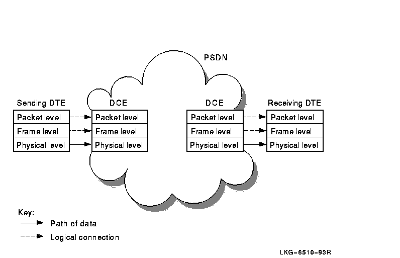
At the sending DTE, data passes down through the levels and each level adds its own control information. When it reaches the physical level, the data is transmitted to the DCE.
At the DCE, the relevant control information is removed as the data passes up through the levels. When it reaches the packet level, data is in the form of X.25 packets, which can now be sent across a PSDN.
When the packets reach the remote DCE, they pass down through the levels and pick up control information. The DCE then sends them to the receiving DTE. At the receiving DTE, the data passes up through the levels.
Each level on the DTE communicates with the corresponding level on the DCE by using the same protocols; therefore, there are logical connections between corresponding levels. They are referred to as logical connections because data is not actually transmitted until it reaches the physical level.
Two DTEs implementing X.25 protocols can exchange data in packets, regardless of the DTE manufacturer. However, once the data is re-assembled in its original format, the receiving DTE may not be able to interpret the message. In this case, additional software may be required to make the data meaningful to the receiving DTE.
4.2.1 Packet Level
This level defines the procedures for formatting packets, sequencing
packets, and establishing virtual circuits. Virtual circuits are the
logical connections between two DTEs (see Section 4.4.2.1).
Most packets contain user data, but some are for control purposes.
Control packets are used for functions such as initiating and
terminating virtual circuits between two DTEs and for interrupt
messages.
The amount of user data allowed in a packet is known as the packet size. The maximum amount of user data allowed in a packet is set by the PSDN you use. A typical packet size is 128 bytes.
Each packet (refer to Figure 4-5) consists of a packet header followed by user data or control information.
Figure 4-5 Structure of a Packet

This level initiates communications between the DTE and the DCE and ensures that data is transferred between DTE and DCE without errors.
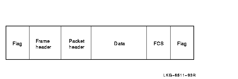
At this level each packet is enclosed within a frame. Each frame consists of:
Figure 4-6 shows the structure of a typical frame.
Figure 4-6 Structure of a Frame
This level defines the mechanical and electrical connections between a
DTE and a DCE. It specifies electrical characteristics, data
transmission speeds, and connector types.
4.3 Implemented Standards
X.25 is a CCITT recommendation that describes a standard for connecting to packet switching networks. The lower three layers of the OSI Reference Model correspond to the three levels in the Comité Consultatif International Téléphonique et Télégraphique (CCITT) X.25 recommendation.
The X.25 standard describes the protocols for the DTE-DCE interface.
4.3.1 Related CCITT Standards
The X.25 recommendation describes only those protocols involved in the DTE-DCE interface to packet switching networks. There are several other CCITT recommendations that are relevant to packet switching, including:
Figure 4-7 illustrates the main packet switching recommendations.
Figure 4-7 CCITT Packet-Switching Recommendations
DECnet-Plus for OpenVMS also implements the following PSDN-related standards from OSI:
4.4 How Connections Are Made and Data Is Transferred
To establish a call and transfer data between DTEs via a PSDN, physical
and logical connections must be made between the calling and called DTE.
4.4.1 Physical Connections
To transfer data, the DTE and DCE must be connected. This connection can take many forms but, in general, the connection is made using a physical line. Two types of line can be used to connect a DTE and a DCE:
The physical line between a DTE and a DCE is divided into a number of logical channels. Logical channels allow many virtual circuits to exist on the physical line. Each logical channel is identified by a logical channel number (LCN), contained in the packet header of every packet sent across a PSDN.
Before data can be sent across a PSDN, a virtual circuit must be established between a logical channel at the calling DTE and a logical channel at the called DTE. The circuits are referred to as "virtual" because a number of virtual circuits may use the same physical circuit to transmit packets from the calling DTE to the called DTE.
It is important to realize that the logical channel used between a DTE and DCE only has local significance. It is the responsibility of the PSDN to map the logical channels used by the calling and called DTEs into an end-to-end virtual circuit. This means that although a virtual circuit has end-to-end significance between the DTEs, different logical channels can be used by the virtual circuit on each side of the PSDN.
This concept is illustrated in Figure 4-8 in which two virtual circuits are depicted. Virtual Circuit A establishes an end-to-end connection using LCN 2 between the calling DTE and its associated DCE, and LCN 1 between the called DTE and its associated DCE. Similarly, Virtual Circuit B establishes an end-to-end connection using LCN 4 on both sides of the PSDN.
Figure 4-8 Virtual Circuits Versus Logical Channels

There are two types of virtual circuits:
A DTE may have many virtual circuits active at the same time over a
single DTE-DCE interface. These circuits can be any combination of PVCs
and SVCs.
4.4.2.2 Logical Channel Numbers
When you subscribe to a PSDN, you are allocated a range of LCNs for the different types of virtual circuits:
An LCN is a 12-bit number. Some PSDNs use the first 4 bits as a
logical channel group number (LCGN) to represent the
use of the channel, and the remaining 8 bits to represent the LCN. Some
PSDNs use the full 12 bits to represent the LCN.
4.4.3 DTE Addresses
Each DTE has an address that the PSDN uses to route calls. DTE addresses are contained in the call request packets and are used for setting up SVCs. The address may be up to 15 digits long and consists of:
DTE addresses may consist of up to 15 digits. However, for internetworking X.121 restricts international data numbers (that is, DTE addresses) to 14 digits.
An example of an X.121 format DTE address is shown in Figure 4-9.
Figure 4-9 DTE Address Example

Some networks use an abbreviated form of addressing to refer to DTEs on
the same network. In such networks, an extra digit is often prefixed to
the DTE address to indicate that the address of the called DTE is on a
different network to the calling DTE.
4.4.4 Controlling the Flow of Packets
When a packet has been received by a called (remote) DTE, the PSDN sends a message to the calling (sending) DTE. This message is known as an acknowledgment. Because of the time it takes a packet to travel across a network, it is inefficient to wait for the acknowledgment of the packet before sending more. For this reason, PSDNs let you send a number of packets before you receive acknowledgment for the first one.
The maximum number of unacknowledged packets you are allowed to have on a virtual circuit is called the window size. Once the window size is reached, and acknowledgments for previously sent packets are received, more packets can be sent. Acknowledgments are often carried by incoming packets of data.
You can specify the window size you want to use, up to the maximum set
by the PSDN. You may want to subscribe to larger window sizes if you
have large amounts of data, or if there is a long delay between sending
a packet and receiving the acknowledgment of that packet.
4.5 Optional Facilities of Public and Private PSDNs
As well as switching packets, each PSDN offers optional facilities to its users. Some must be subscribed to, and others must be requested at the time the call is set up. A specific PSDN may support additional facilities that are not defined by the CCITT. A full list of such facilities can be obtained from the PSDN supplier.
According to CCITT X.25 (1984), these facilities fall into three categories:
DTE parameters govern the frame- and packet-level operation of DTEs.
They specify properties such as window size and packet size. Various
PSDNs support different parameters. For more information on the
parameters supported, contact your PSDN supplier.
4.5.2 PAD Parameters
PSDNs offer optional PAD facilities that are represented by variables known as PAD parameters. You can set PAD parameters to indicate that you want to use a PAD facility and how you want to use it.
A set of PAD parameters is a profile; most networks define several profiles to suit different types of character-mode DTEs (X.29 terminals). When you connect to a PAD, you can select a profile to control the actions of the PAD. During a call, you can read and reset most of the PAD parameters.
Refer to the X.25 for OpenVMS Management Guide which describes
the CCITT-defined PAD parameters, all supported by DECnet-Plus for
OpenVMS.
4.6 Network Profiles
Digital supports the use of its X.25 products with a number of public and private PSDNs. A network profile contains the information necessary to support a particular PSDN including network parameters pertinent to a specific network. For example, it contains the default value and permissible range of values for the X.25 window size.
Details of the PSDNs supported by Digital's X.25 products can be
obtained from your Digital representative. For details of the
permissible network parameters for a specific network, refer to the
documentation provided by your PSDN supplier.
4.7 PSDNs Supported by Digital's X.25 Products
Before a PSDN is supported by Digital, it has to go through Digital's own testing procedure. This is necessary to determine the network parameters to store in the associated network profile. The testing procedure produces a network profile for each PSDN. If you use the correct profile for the PSDN you are connecting to then your communications will be successful, and Digital will provide you with support in the event of any problems.
If you want to use a PSDN that is not currently supported by Digital, you can ask Digital to provide support for the network. Digital will then test the PSDN and produce a network profile for use with the PSDN. Your local Digital office can provide details on how this support service is provided.
Part III provides information on using remote files with DECnet-Plus, using the DECnet-Plus login utility, and sending mail to DECnet-Plus nodes. This section includes the following chapters:
This chapter explains the functions you can perform in a DECnet network
environment including remote login, file, and mail operations. It also
explains how to develop command procedures and application programs
that run over the network.
5.1 How You Can Use DECnet
You perform network operations as a natural extension of the input/output operations you perform on your own local system, because DECnet-Plus for OpenVMS networking capabilities are completely integrated into the operating system.
With appropriate access on a remote node, you can carry out general
user operations over the network as easily as at the local node. Most
DECnet-Plus for OpenVMS file-handling commands permit you to access
files on remote systems in the same way as files on your own system as
long as you have appropriate access.
5.1.1 Performing Operations using DCL Commands
You can use DCL commands to perform the following DECnet-Plus for OpenVMS operations over the network:
$ help decnet_osi
Node synonyms are required for layered products and utilities that do
not yet support DECnet-Plus full names. Full name support is available
for the SET HOST and Mail utilities, and for most DCL commands that use
file specifications (such as COPY, DIRECTORY, etc.) and some utilities
that use RMS.
5.2.1 Phase IV-Style Node Synonyms
Because a full name consists of the complete directory path from the root directory to the target object entry, directory, or soft link, full names can be long if a namespace has several levels of directories.
DECnet-Plus supports a 6-character Phase IV-style node name called the node synonym. A node synonym is a soft link that points to the full name of a node object entry. Node synonym soft links enable applications that do not support the length of full names to continue to use 6-character node names.
Node synonyms should not be viewed as a way for users to avoid typing
the full name of a node. Logical names, and a feature called the local
root, are faster and more convenient methods of shortening names. Both
logical names and local roots are for use only on the system where they
are defined; unlike node synonyms, they do not have global meaning
throughout the namespace. Also, logical names and local roots can be
used to name any resource (such as a disk or an application), not just
node names.
5.2.2 Name Abbreviation Using Local Roots
The local root is a prefix that DECnet-Plus obtains automatically by stripping off the rightmost simple name of the local node's DECnet-Plus full name. For example, a node named IAF:.DIST.QA01 would have IAF:.DIST as its local root. Users will likely want to refer frequently to other names in the hierarchy in which their local node is named. The local root capability makes such name references more convenient by allowing users to omit the part of the full name that is also part of their node's full name.
DECnet-Plus Session Control creates the local root under the fixed name
dnsroot in the dns$system logical name table.
5.2.3 Logging In to Other DECnet Nodes
To gain access to the network, log in to your account on the OpenVMS system. Before you perform an operation over the network, you can check the availability of the network by entering the following command:
$ show logical net$startup_status

   "net$startup_status" = "running-all" (lnm$system_table)
![[HR]](../../IMAGES/REDBAR.GIF)
  INTRO_PROFILE_006.HTML
  OSSG Documentation
   2-DEC-1996 12:54:26.71
Copyright © Digital Equipment Corporation 1996. All Rights Reserved.