![[Digital logo]](../../IMAGES/DIGITAL-LOGO.GIF)
![[HR]](../../IMAGES/REDBAR.GIF)
![[Digital logo]](../../IMAGES/DIGITAL-LOGO.GIF)
![[HR]](../../IMAGES/REDBAR.GIF)
An OSI application entity's PSEL, SSEL, and TSEL are arbitrary octet strings defined during configuration. The network service access point (NSAP) represents the address. It is not subdivided for lower layer addressing. However, it may be derived from a lower layer address to ensure uniqueness. Section 8.8.2.1 explains the contents of NSAP addresses for X.25 CONS networks. A single node can have more than one NSAP address.
For a successful connection, an OSI application specifies to the Presentation layer the responder's PSEL, SSEL, and TSEL along with one of the destination NSAPs. Table 8-11 describes the contents of each part of an OSI application address.
| Component | Size | Required | Structure | Example |
|---|---|---|---|---|
| AP-Title | Unrestricted | No | Object Identifier | {1 3 9999 1 7} |
| AE-Qualifier | 1 - 4 octets | No | Integer Number | 1 |
| PSEL | 0 - 4 octets | No | Hexadecimal string | %X'0001' |
| SSEL | 0 - 16 octets | No | Hexadecimal string | %X'0001' |
| TSEL | 0 - 32 octets | No | Hexadecimal string | %X'0001' |
| NSAP | 2 - 20 octets | Yes | See Section 8.8.2.1 | 3600234212345678 |
X.25 CONS Network Connections
This section describes X.25 CONS connections and addressing. Figure 8-11 shows a worldwide network owned and operated by interconnected PTTs and telephone companies. Connections between nodes resemble telephone calls. Digital's X.25/WAN products allow OSI client applications to "call" services anywhere in the worldwide X.25 network (represented by the cloud in Figure 8-11) without management intervention. The data terminal equipment (DTE) boxes are the initiator and responder nodes shown in Figure 8-10. The Packet Switched Data Network (PSDN) and the PSDN interface software on the DTE's together comprise the OSI network layer in an X.25 CONS network.
Figure 8-11 X.25 CONS Network

To initiate a call, a DTE sends a call request packet to the X.25 network. An X.25 call request packet contains the following fields to support addressing:
DTE Address Fields
The definition of a "DTE address" depends on the context. A DTE address passed at the DCE/DTE boundary can differ from a DTE address passed between two X.25 networks. In this document, the DTE address passed between an X.25 service user and an X.25 service provider at the DCE/DTE boundary is called an "X.25 network address."
The calling and called DTE address fields contain the source and destination X.25 network addresses. They are usually the only address fields used by public PSDNs to set up a call. An X.25 network address is a series of decimal digits that resembles a telephone number. A digit is encoded in a four-bit nibble with values ranging from 0000 to 1001. Two digits fit in each octet. Each address has a corresponding length field that specifies the length in digits. Some digits represent the country code, others represent the network code and local network connection. As with telephone numbers, number sequences for making local calls within a single X.25 network and long distance calls between X.25 networks vary among various PTTs and telephone companies.
An NSAP can always be mapped to an X.25 network address. Mapping an X.25 network address back to an NSAP is not always possible. See below for a discussion of address mapping and how to construct an NSAP address that can be derived from an X.25 network address.
Address Extension Facilities
X.25 supports many optional functions or "facilities" during call setup and clearing. The calling and called address extension facilities transfer upper layer addresses between X.25 users at each end of a call. For the X.25 CONS protocol stack, these facilities transfer complete NSAP addresses between the initiator and responder of a call.
Address extension facilities allow a system manager to assign any NSAP address to a node independently of the X.25 network address. All DECnet-Plus platforms support address extension facilities. However, these facilities are not universally supported by all X.25 networks nor by all other X.25 DTE implementations. Do not rely on them to pass NSAPs across the network, unless you have no other alternative, and you know that all parties in the connection support them.
The first byte of an address extension facility contains an integer representing the length of the NSAP in digits. The remaining bytes of an address extension facility contains the NSAP. For example, the NSAP 36002342123456781234 contains 20 digits. The equivalent address extension facility is %X14360023421234561234.
Call User Data
Many X.25 DTE implementations can use the call user data field of an incoming call packet to identify the intended X.25 application. The CCITT X.224 Annex B standard requires that the call user data field for calls to OSI transport be set to %x03010100. This value represents the following:
NSAP to X.25 Address Translation
OSI applications use NSAPs to address other nodes. X.25 communicates using X.25 network addresses. Addressing complications arise because various X.25 network service providers do not use a consistent X.25 network addressing scheme. CCITT X.121 is the network addressing standard that PSDNs use to communicate with each other. Some X.25 PSDN service providers use this addressing scheme directly. Others use an abbreviated form of X.121 for calls within their network.
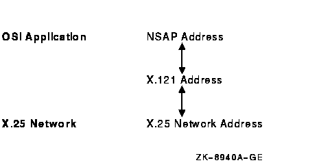
Figure 8-12 shows the address translation steps taken from an NSAP used by OSI applications to an X.25 network address in an X.25 call packet. Digital's X.25 and X.25 Access software product components provide mechanisms to handle all these translations.
Figure 8-12 X.25 CONS Address Translations

X.121 Addresses
X.121 describes the international numbering plan for public data networks (X.25 networks). Equivalent international numbering plans exist for the telephone and telex networks.
X.121 defines a four-digit data network identification code (DNIC) for identifying X.25 networks. The DNIC is composed of a three-digit data country code (DCC) identifying the country followed by a single digit to distinguish among multiple networks within a country. X.121 allocates DCCs to countries, such as 234 and 235 for the United Kingdom, 310 to 316 for the United States of America, and 505 for Australia. Because 505 is the DCC for Australia, the two DNICs 5052 and 5054 identify two distinct X.25 networks within Australia. DNICs (and DCCs) begin with one of the digits 2 through 7 inclusive. The initial digits 0, 1, and 8 are reserved for other purposes. The maximum length of an X.121 address is 14 digits.
An X.121 address takes one of two forms:
Figure 8-13 X.121 Address with Four-Digit DNIC and NTN of up to 10 Digits

Figure 8-14 X.121 Address with Three-Digit DNIC and NN of up to 10 Digits

Local Subaddresses
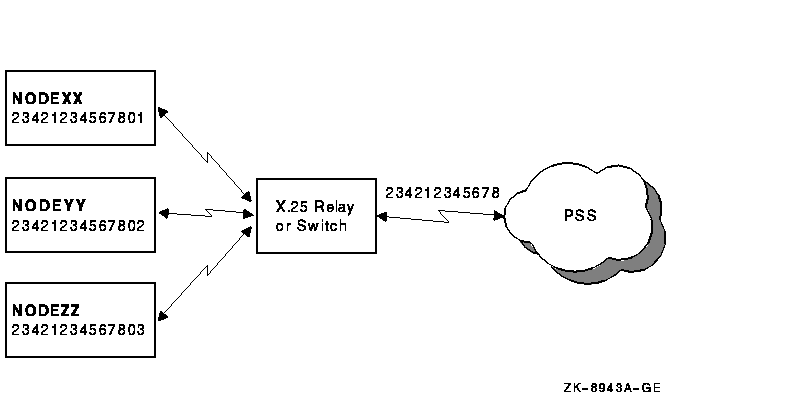
X.25 Network providers often do not use the full 14 digits allowed for an X.121 address. They typically leave two digits at the end of the address for assignment by the service subscriber. In configurations where multiple nodes are attached to a single X.25 line, the Local Subaddress can be used to identify a particular node. For example, a subscriber to PSS in the United Kingdom with the X.25 network address 234212345678 might set up the configuration shown in Figure 8-15 with an X.25 relay or switch.
Figure 8-15 Use of Local Subaddresses

All the nodes share the same PSS X.25 network address of 234212345678, but they each have a separate local subaddress of 01, 02, and 03. A node attempting to call NODEYY would use the destination address 23431234567802.
X.25 Network Addresses
Three major types of addressing conventions are used in X.25 networks to describe the conversion between the globally unique X.121 addresses and the addresses actually used on the network. The three conventions are X.121 addresses, national number (NN-based) addresses, and national terminal number (NTN-based) numbers.
| Call Destination | X.121 Address | X.25 Network Address |
|---|---|---|
| Within PSS | 234212345678 | 234212345678 |
| Across networks to AUSTPAC | 505287654321 | 505287654321 |
| Across networks to PACNET | 530187654321 | 530187654321 |
| Call Destination | X.121 Address | X.25 Network Address |
|---|---|---|
| Across networks to PSS | 234 212345678 | 0 234 212345678 |
| Within AUSTPAC | 505 287654321 | 287654321 |
| Across networks to PACNET | 530 187654321 | 0 530 187654321 |
| Call Destination | X.121 Address | X.25 Network Address |
|---|---|---|
| Across networks to PSS | 2342 12345678 | 0 2342 12345678 |
| Across networks to AUSTPAC | 5052 87654321 | 0 5052 87654321 |
| Within PACNET | 5301 87654321 | 87654321 |
NSAP Addresses
The structure of an OSI NSAP address is defined in ISO/IEC 8348:1993 Annex A. Figure 8-16 shows this structure.
Figure 8-16 NSAP Address Structure

Every NSAP address has two primary fields:
| First X.121 Digit | DSP Syntax | AFI Value | IDI Padding | Example X.121 Address | Corresponding IDI |
|---|---|---|---|---|---|
| non-zero | decimal | 36 | zeros | 234212345678 | 00234212345678 |
| non-zero | binary | 37 | zeros | 234212345678 | 00234212345678 |
| zero | decimal | 52 | ones | 06175750100 | 11106175750100 |
| zero | decimal | 53 | ones | 06175750100 | 11106175750100 |
Table 8-16 shows example NSAP addresses using the same X.121 addresses listed in Table 8-12 for PSS, AUSTPAC, and PACNET. You can use these NSAPs over any X.25 network. The AFI is shown in bold type, the IDI in italics. The DSP was left null for these NSAPs.
| Call Destination | X.121 Address | NSAP |
|---|---|---|
| PSS | 234212345678 | 36 00234212345678 |
| AUSTPAC | 505287654321 | 36 00505287654321 |
| PACNET | 530187654321 | 36 00530187654321 |
ISO Conversion Rules
ISO/IEC 8878:1987 defines which NSAP/X.25 network address conversions are allowed. Loosely translated, the calling node can omit the address extension facilities if the NSAP addresses map directly to X.121 addresses: the DSPs must be null, the AFIs must be those shown in Table 8-15, and the IDIs must contain the complete X.121 addresses.
The called node must be capable of accepting a call with or without
address extension facilities. If the facilities exist in the call, X.25
passes the NSAP addresses in the facilities up to the Transport layer.
If the facilities do not exist, X.25 must derive the NSAP addresses
from the X.121 addresses of the incoming call.
8.8.2.2 X.25 CONS Management Entities
You cannot configure the X.25 CONS protocol stack on DECnet-Plus end system products using the configuration tools alone. To successfully configure the stack, you must understand NCL and the management entities in the X.25 CONS stack. Table 8-17 shows the management entities used at each layer of the protocol stack.
The X.25 and LAPB protocols allow many options that vary among X.25 networks. Digital's products provide X.25 network profiles that contain all the pertinent network parameters for most PSDNs. For example, profiles contain the default value and permissible range for the X.25 window size. The system administrator specifies the profile name during system configuration. Typically, the profile name corresponds to the name of the PSDN.
The X.25 and X.25 Access software components follow instructions from both their user applications and their management entities. You cannot control the behavior of these components entirely by management. In some cases, X.25 and X.25 Access software ignore certain management parameters, depending on which functions an X.25 application uses.
| Protocol Layer | Management Entity | Function in CONS Stack |
|---|---|---|
| ACSE, Presentation, and Session |
osak
osak application osak application invocation |
Defines the OSI application's ACSE, Presentation, and Session addresses for incoming connections. |
| Transport Class 0 |
osi transport
osi transport application osi transport port osi transport template |
Defines which outgoing connections pass through X.25. Routes incoming requests to OSAK based on the TSEL. |
| X.25 Packet Layer |
x25 access
x25 access application x25 access dte class x25 access filter x25 access port x25 access reachable address x25 access security dte class x25 access security filter x25 access template x25 access protocol x25 protocol dte |
Translates between NSAP and X.25 network addresses. Establishes a connection to the X.25 network service provider. Routes incoming calls to OSI transport, based on received X.25 call packet contents. Controls access from the X.25 network to the computer system. |
| LAPB Link Layer |
lapb
lapb link lapb port |
Controls datalink buffers and timers. |
| Modem Connect |
modem connect
modem connect line modem connect data port |
Controls physical attributes of the modem connection. |
Example Configuration
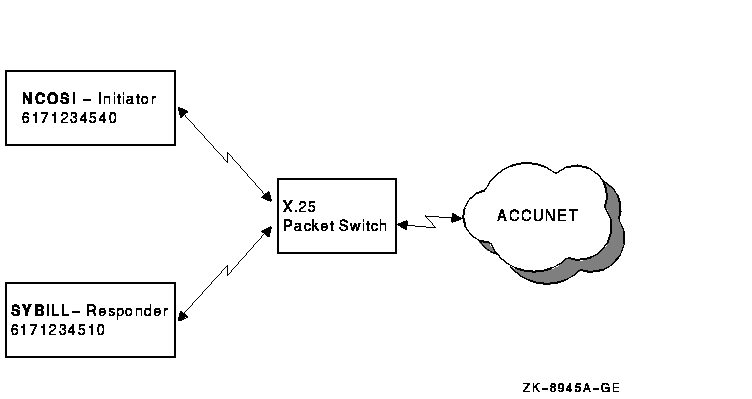
The following illustrated configuration and the examples that follow help clarify the interrelationships among management entities for outgoing and incoming calls using X.25 CONS. Assume the end system implementations NCOSI and SYBILL are connected to a local X.25 packet switch, which in turn is connected to an AT&T Accunet line, as shown in Figure 8-17.
Figure 8-17 Example Configuration

Accunet addresses are NTN-based, similar to PACNET. All addresses discussed in this section are based on conversion rules defined in international standards.
NCOSI is set up as the OSI application initiator, SYBILL as the responder. AT&T assigned a range of addresses to the line from 6171234500 to 6171234599.
The Accunet DNIC is 3134, and the international prefix is 0. NCOSI has a local subaddress of 40, and SYBILL has a local subaddress of 10. From these subaddresses, the remaining addresses are derived using the conversion rules explained in Section 8.8.2.1. Table 8-18 lists these addresses.
| Source: NCOSI | Destination: SYBILL | |
|---|---|---|
| Accunet DNIC | 3134 | 3134 |
| Accunet Line Address | 6171234500-99 | 6171234500-99 |
| X.25 Profile | Accunet | Accunet |
| Local Subaddress | 40 | 10 |
| X.25 Network Address | 61712345 | 61712345 |
| X.121 Address | 31346171234540 | 31346171234540 |
| Address Extension Facility | 103631346171234540 | 103631346171234510 |
Figure 8-18 shows the entity relationships for outgoing connections. The following actions occur during an outgoing call:
![[HR]](../../IMAGES/REDBAR.GIF)
  PROFILE_VMS_013.HTML
  OSSG Documentation
   2-DEC-1996 12:35:07.21
Copyright © Digital Equipment Corporation 1996. All Rights Reserved.