![[Digital logo]](../../IMAGES/DIGITAL-LOGO.GIF)
![[HR]](../../IMAGES/REDBAR.GIF)
![[Digital logo]](../../IMAGES/DIGITAL-LOGO.GIF)
![[HR]](../../IMAGES/REDBAR.GIF)
3.1.2 Using Loopback Tests on Phase IV Nodes
To perform loopback tests when logged in to a Phase IV node, use NCP
commands (see your DECnet Phase IV documentation for details). To
perform loopback tests when logged in to a DECnet-Plus node, use NCL
commands, even if you are testing a remote Phase IV node.
3.1.3 Types of dts/dtr Tests
The dts/dtr program provides the following basic tests:
| Test | Description |
|---|---|
| Connect test | Verifies that the receiving node ( dtr node) can process connection requests and return acceptance and rejection messages with or without optional user data. |
| Data test | Provides a full range of tests from very simple data sink operations through data integrity checking. |
| Disconnect test | Verifies that the receiving node ( dtr node) can send out disconnect messages with or without optional user data. |
| Interrupt test | Provides a full range of test capabilities from very simple data sink operations through data integrity checking. |
DECnet/OSI for Digital UNIX implements an OSI Echo function (OSI ping). This function enables an ISO 8473 network-entity to generate a special type of PDU, the Echo Request PDU, also known as OSI ping, which is sent to the requested destination in order to elicit an Echo Response PDU from that destination.
This implementation supports both RFC 1139 and Amendment X to ISO 8473.
It is important to realize that not all OSI systems support the OSI
Echo function. Consequently, an attempt to ping such a system will not
succeed even though that system is functioning normally.
3.2.1 OSI ping Command Syntax
The OSI ping command syntax is:
/usr/sbin/oping[options] host [datasize] [npackets]
The host is a DECnet/OSI node name, node synonym or NSAP (preceded by %x). For example:
            abc:.xyz.node1
            node1
            %x49000caa000400192000
The following table describes the optional arguments for this command:
| Option | Description | ||||
|---|---|---|---|---|---|
| Options |
|
||||
| datasize | If no data size is specified, the default value of 64 bytes is used for the data portion. | ||||
| npackets | If no npackets are specified and the -l option is used, oping will send approximately 1 echo request per second until stopped by the user. If npackets is specified, exactly npackets echo requests will be sent. |
Several different implementations of OSI Echo function exist in the industry. Before Amendment X to ISO8473 existed, various vendors implemented RFC 1139 (an Echo function for ISO 8473).
RFC 1139 offers two possible implementation mechanisms. The first, called "The Short Term Implementation Mechanism" uses special NSAP selectors in the data PDUs conveying the echo messages. The second, called "The Long Term Implementation Mechanism," uses special PDU types for Echo request and Echo Response PDUs.
Amendment X to ISO 8473 implements the "Long Term Mechanism" which OSI
ping uses by default. To interoperate with the "Short Term
Implementation Mechanism", use the -s option if an attempt to
ping a system using the default mechanism fails.
3.3 Node-Level Loopback Tests Overview
Use the node-level loopback tests first; if further testing is desired,
use the circuit-level loopback tests.
3.3.1 When to Use Node-Level Loopback Tests
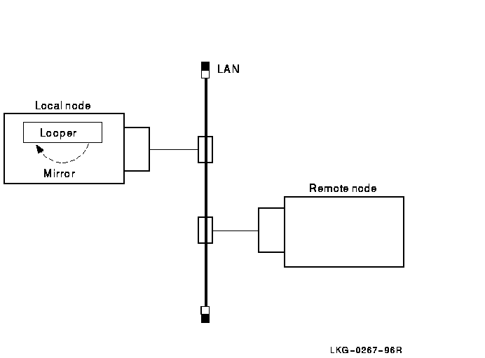
Use the local-to-local loopback test to verify operation of the local Network, Application, Session Control, Transport layers, and part of the Routing layer.
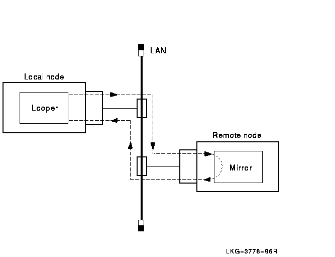
Use the local-to-remote loopback test to verify operation of all levels
of network software on the local and remote nodes you are testing.
3.3.2 Analyzing Local-to-Local Node Loopback Test Results
If a looped message returns with an error, the test stops and NCL displays a message specifying the reason for the failure. If the loopback test completes successfully, there is no output.
A failure of this test indicates a problem with the local node software, such as the network being turned off or access control to the mirror not being properly established. If the local-to-local loopback test fails, check the log file for additional information on the cause of the failure.
If the local-to-local loopback test succeeds, perform a local-to-remote
loopback test. If the local-to-remote test fails, try the circuit-level
tests to determine if the hardware is at fault.
3.3.3 Log File for Local-to-Local Node Loopback Tests
The OpenVMS log file for local-to-local loopback test failures is net$server.log. You find this file in the mirro$server account if you set up a mirror account when you installed the DECnet-Plus software. If the mirror account does not exist, the location of the net$server.log file depends on the type of account from which the test is initiated.
For example, if the account from which the test initiates has an account on the target system, then the net$server.log file is located in the account on the target system. If this account does not exist on the target system, the connection is not completed. Additionally, if the initiating system uses a proxy account to connect to the target system, then the net$server.log file is found in the proxy account.
The Digital UNIX log file for local-to-local loopback test failures is
/usr/adm/syslog.dated/dd-mmm-hh.mm/daemon.log.
3.3.4 Local-to-Local Node Loopback Figure
Figure 3-1 illustrates a local-to-local loopback test.
Figure 3-1 Local-to-Local Loopback Test
If the previous local-to-local tests were successful and this test
fails, a problem exists with either the remote node or the network. Try
the test again with a different remote node. If the second test
succeeds, a problem with the first remote node that you used probably
caused the failure. If the test fails, a network problem probably
caused the failure.
3.3.6 Local-to-Remote Loopback Test Figure
Figure 3-2 illustrates a local-to-remote loopback test.
Figure 3-2 Local-to-Remote Loopback Test
When you start this test, identify the node to which you want to loop test messages with the node's full name. This node must be reachable over circuits that are in the On state.
Use the following NCL command to start a node-level loopback test:
ncl>loop [node node-id] loopback application
[parameter,] -
_ncl>name node-id
The nodenode-id parameter identifies the node from
which you start the test. The default value of this parameter is 0. The
namenode-id parameter identifies the node to which
you want to loop.
3.4.1 Node-Level Loopback Command Parameters
You can specify any of the following optional parameters:
| Parameter | Description |
|---|---|
| format | Specifies the type of binary information used to perform the test. Specify this value as a pair of hexadecimal digits such as format=FF. The hexadecimal value 55, a combination of ones and zeros, is the default. |
| count | Specifies the number of data blocks to be sent during the test. Specify a number from 1 (default) through 65,535. |
| length | Specifies the length in bytes of each block to be looped. This value must be a decimal integer from 1 through n. The value of n must be less than the smaller buffer size of the two tasks involved in the test. The default is 40 bytes. |
In the following test, a network manager attempts to loop 10 messages to node BOSTON. The result is that the message is not looped because node BOSTON is unreachable.
ncl> loop loopback application count 10, name boston
node 0 Loopback Application at
                 1991-04-22-13:00:27.725-04:00I0.212

FAILED IN DIRECTIVE: Loop DUE TO: Error specific to this
                 entity's class

REASON: Connection Failed
Description: The Connection to the remote mirror failed
ncl>
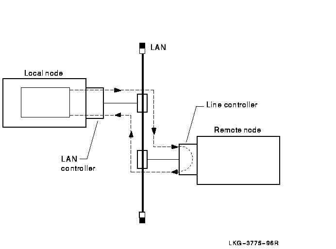
These tests use a low-level data link interface rather than the logical links used by the node-level tests. They use DECnet software to loop data through the circuit-to-circuit service software in the adjacent node and back to the local node. You can specify optional parameters for assistance in testing a remote node (see Section 3.8.4).
On non-LAN circuits, you can loop test data through a passive loopback
connector or through an active remote system. On LAN circuits, the
remote system ultimately returns the test data.
3.5.1 Circuit-Level Loopback Test Figure
Figure 3-3 illustrates a circuit-level loopback test.
Figure 3-3 Circuit-Level Loopback Test
Unique Ethernet addresses identify nodes on Ethernet circuits. If the
node is running DECnet Phase IV, or is a DECnet-Plus node that has a
Phase IV node synonym, this physical address is the one that DECnet
created using the DECnet node address. If the node is not running
DECnet, the physical address is the default hardware address of the
node.
3.6 Preparing for Circuit-Level Loopback Tests
Do the following before you run a circuit-level software loopback test:
| Step | Action |
|---|---|
| 1 | Use the NCL command show mop state to check that the mop entity is in the On state. |
| 2 | Use the NCL command show mop circuit* name, function to check that the circuit to be tested has loop requester function enabled. |
| 3 | If the mop entity or the circuit is not in the appropriate state, use the NCL commands create mop circuit circuit-id type type-id to start them. For example, you could use the following commands: |
|
ncl>create mop circuit csmacd-0 type csma-cd
This creates the MOP circuit, csmacd-0. |
|
|
ncl>set mop circuit csmacd-0 link name -
_ncl>csma-cd station csmacd-0 This customizes the entity definition for the circuit csmacd-0. |
|
|
You can also start them with an NCL command script,
such as /var/share/dna/scripts on a Digital UNIX system. |
|
| On an OpenVMS system, you can use: @sys$system:startup network mop | |
| 4 |
Determine the physical device associated with a
mop circuit as follows:
|
In this example, the output from the NCL commands shows:
(1) ncl> show mop state

Node 0 MOP
AT 1994-1-04-1-13:27:12/325-05:00I0.176

Status

   State      = On


(2) ncl> show mop circuit * name, function

Node 0 MOP Circuit *
AT 1994-04-1-13:27:30.095-05:00I0.178

Identifiers

   Name       = circuit-1

Status

   Functions      = {
                          Loop Requester,
                          Load Requester,
                          Load Server,
                          Dump Server
                          }

(3) ncl> show mop circuit circuit-1 all char

Node 0 MOP Circuit circuit-1
AT 1992-04-01-13:38:27.747-05:00I0.198

Characteristics

    Type   = CSMA-CD
    Link Name   = CSMA-CD Station csmacd-1
    Retransmit Timer  = 4
    Known Clients Only  = False

ncl> show csma-cd station csmacd-1 all status

Node 0 CSMA-CD Station csmacd-1
AT 1992-04-01-13:39:27.557-05:00I0.204

Status

    UID    = 535AD8E0-F037-11C9-B60F-08002B16A872
    Communication Port  = xna0
    Hardware Address         = 08-00-2b-16-a8-72
    State   = On
    MAC Address   = aa-00-04-00-50-30
    Receive Mode  = Normal
Use the NCL command loop mop circuitcircuit-id [parameter] or loop mop client client-id to start a circuit-level loopback test.
Typically, you specify a client entity unless you need to test communication with a system that has no corresponding client entity. The circuit-level loopback command parameters are the same for both commands.
If you specify a LAN circuit, specify the address for the target communications hardware. For example, you enter:
ncl>loop mop circuit circuit-1 address -
_ncl>AA-00-04-00-79-34
If you specify a synchronous or asynchronous circuit (for example, HDLC
or DDCMP) you do not need to specify the address.
3.7.1 Circuit-Level Loopback Command Parameters
You can specify any of the following parameters:
| Parameter | Description | ||||||||
|---|---|---|---|---|---|---|---|---|---|
| format | Specifies the type of binary information used for the test. This is specified as a pair of hexadecimal digits such as format=FF. The hexadecimal value 55, a combination of ones and zeros, is the default. | ||||||||
| count | Specifies the number of data blocks to be sent during the test. It is a number from 1 (default) through 65,535. | ||||||||
| length |
Specifies the length (in bytes) of each block to be looped. This value
must be a decimal integer in the range of 1 through
n, where
n is determined by the circuit and buffer sizes available on
the local and remote systems. On the Ethernet, the allowable length is
from 1 byte to the maximum length of the data pattern, which varies
according to the level of assistance. The default is 40 bytes.
|
||||||||
| assistant address | Specifies the address of the system to be used as an assistant node. An assistant node is a remote system that helps you interrogate another remote node. | ||||||||
| assistant system | Specifies the node-id of the system to be used as an assistant node. Use this only for LANs. | ||||||||
| assistance type | Specifies the level of assistance you want to use (see Section 3.8.4.) |
In this test, the software attempts to send 10 messages through the circuit called circuit-1.
ncl> loop mop circuit circuit-1 address aa-00-03-00-ff-08, count 10
DECnet supports the use of an assistant node to aid you in
interrogating a remote node. You can use the assistance feature for LAN
circuits only.
3.8.1 When to Use Assistance
You might choose one form of assistance over another for the following reasons:
Running the circuit-level loopback tests with assistance in the following order can help you isolate connection problems:
Use one of the following NCL commands to start a circuit-level loopback test with assistance:
ncl> loop mop circuit circuit-id address address -
_ncl> assistance type [assistance type]
If you already defined a MOP client with circuit and address attributes, omit the circuit-id and address parameters and just identify the client as follows:
ncl> loop mop client client-name
If no MOP client is defined:
ncl> loop mop circuit circuit-id address address, -
_ncl> assistance type [assistance type]
When you specify either the assistant system or assistant address parameter without an assistance type, you receive full assistance by default. The following table describes the assistance type values:
| Assistance Type Value | Description |
|---|---|
| assistance type none | No assistance is used. |
| assistance type full | This assistance type aids in transmitting loop messages to and receiving messages from a remote node (default value). |
| assistance type receive | This assistance type aids in receiving loop messages from a remote node. |
| assistance type transmit | This assistance type aids in transmitting loop messages to a remote node. |
Example of Assistant Address Command
In this example, you request the node described by the LAN physical address AA-00-04-00-15-04 to assist you in testing the node described by the LAN physical address AA-00-04-00-18-04. Because assistant address is specified without the assistant type parameter, full assistance is given.
ncl>loop mop circuit circuit-1 address aa-00-04-00-18-04, -
_ncl>assistant address aa-00-04-00-15-04
Example of Assistant System Command
In this example, you request node THRUSH to assist in testing node LOON by transmitting the loopback data to node LOON. THRUSH must already be defined in the MOP client database, with a value for its circuit and address.
ncl>loop mop client loon, assistant system -
_ncl>thrush, assistant type transmit
3.8.5 Example of Circuit-Level Loopback Test with Full Assistance
Figure 3-4 illustrates a loopback test between the circuit for Node1 and Node3, with Node2 providing assistance. The NCL command is:
ncl>loop mop client Node3, assistant system Node2
Figure 3-4 Circuit-Level Loopback Test with Full Assistance
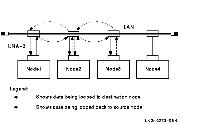
Figure 3-5 illustrates a loopback test between Node1 and Node3, with Node2 providing transmit assistance. The NCL command is:
ncl> loop mop client Node3, assistant system Node2, -
_ncl> assistance type transmit
Figure 3-5 Circuit-Level Loopback Test with Transmit Assistance
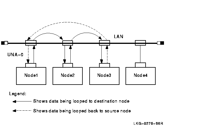
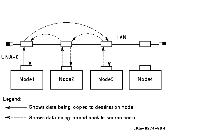
Figure 3-6 illustrates a loopback test between Node1 and Node3, with Node2 providing receive assistance. The NCL command is:
ncl>loop mop client Node3, assistant system Node2 -
_ncl> assistance type receive
Figure 3-6 Circuit-Level Loopback Test with Receive Assistance
This test allows you to perform LAN loopback tests that use IEEE 802.3
logical link control (LLC) test messages.
3.9.1 Starting the LAN Loopback Test
Do the following to start a LAN loopback test:
| Step | Action |
|---|---|
| 1 | Make sure the circuit you want to test has the Test Requester function enabled. |
| 2 |
Enter one of the following NCL commands:
ncl>test mop circuit
circuit-id address -
ncl>test mop client client-name [ parameter] Typically, you specify a client entity, unless you need to test communication with a system that has no corresponding client entity. The LAN loopback test command parameters are the same for both commands. |
The following table describes the test command parameters for the LAN loopback test:
| Parameter | Description |
|---|---|
| count count |
Specifies the number of messages you want to loop. The default is 1.
If the test fails, NCL displays the number of messages that successfully looped. |
| length length | Specifies the length of the data part of each test message. The maximum and minimum permitted values depend on the particular data link that you use. The default is 40. |
| format format | Specifies the value of each byte in the test data message. The hexadecimal value 55, which is a pattern of alternating ones and zeros, is the default. |
| sap sap | Specifies the service access point on the target system to which the test message is sent as 2 hexadecimal digits. The default is 00. |
You can use the NCL command query to determine the logical link control (LLC) types that a remote system supports. The query command sends an IEEE 802.2 LLC XID command to a remote system and receives an XID response in return. The circuit must have the Query Requester function enabled before you can use the query command.
![[HR]](../../IMAGES/REDBAR.GIF)
  PS_PROFILE_002.HTML
  OSSG Documentation
   2-DEC-1996 12:34:14.14
Copyright © Digital Equipment Corporation 1996. All Rights Reserved.