![[Digital logo]](../../IMAGES/DIGITAL-LOGO.GIF)
![[HR]](../../IMAGES/REDBAR.GIF)
![[Digital logo]](../../IMAGES/DIGITAL-LOGO.GIF)
![[HR]](../../IMAGES/REDBAR.GIF)
When planning replication in large networks, consider the following guidelines to enhance DECdns performance:
The following are specific guidelines for replicating the directories that contain node object entries, node synonyms, and backtranslation soft links:
To ensure its ability to find names, DECdns enforces some rules regarding clearinghouses and their contents. The DECnet-Plus DECdns Management guide contains an appendix that explains the rules in detail. For planning purposes, the main rule to remember is that whenever a clearinghouse is named in the root directory, the root is automatically replicated in that clearinghouse. In a network with more than 50 DECdns servers, naming all clearinghouses in the root could, therefore, cause replication of the root beyond a practical limit. Naming some clearinghouses in directories below the root helps to avoid this problem.
For instance, if you have 50 clearinghouses in a network and you name them all in the root, the root directory is replicated in at least 50 places to comply with the rule. Then, every time DECdns skulks the root directory it must be able to contact and process all 50 replicas. The greater the number of replicas, the greater the demand on system and network resources, and the greater the chance for skulks to fail. Skulks also can fail if a directory is replicated across an unreliable WAN link.
Therefore, if your namespace will have more than 50 clearinghouses, you can help avoid problems with replicating and skulking the root by naming some clearinghouses in lower-level directories. Naming a clearinghouse in a directory other than the root eliminates the requirement that a replica of the root be stored there, thus reducing the total number of root replicas in the network.
If your namespace is easily divisible by geographic area, you could
create some geographic directories under the root and name
clearinghouses in those directories; for example,
.Tokyo.Site1_CH, .Wash.Seattle_CH, or
.Paris.Branch3_CH. The geographic directories in each
clearinghouse could also contain data used primarily by the people and
applications in that geographic area, and the work of skulking replicas
would be more evenly distributed than if all of the data were in the
root.
8.3 DECdns Server Capacity Planning
To determine whether a node has the capacity to be a DECdns server, consider several factors, including the system's disk space and processing power, the demand that other applications already place on the system, and the demand you expect from DECdns.
If you expect high DECdns lookup and update demand, consider using a dedicated server. Digital recommends using dedicated servers for large networks, because a dedicated system generally boots faster than a timesharing system, and you can select it specifically for optimum DECdns server performance. For example, you will probably have to increase the swap space on a server with a clearinghouse that contains many directory replicas or replicas with many entries. Keep in mind that a few large, dedicated servers can perform better than many small timesharing systems.
To estimate capacity requirements for a server, assess the number of directory replicas to be stored at each server and the number of entries in those replicas. Table 8-1 contains estimates of memory usage for ACEs, directories, node object entries, and soft links.
| Item | Memory |
|---|---|
| ACE | 60 bytes |
| Node object entry | 750 bytes |
| Node synonym soft link | 520 bytes |
| Backtranslation soft link | 520 bytes |
| Directory | 4700 bytes |
The numbers in the table are based on the following assumptions:
If you plan node names of 30 characters or longer, or if you expect principal names to be longer or shorter than 20 characters, adjust the capacity estimates accordingly. Also remember that a lengthy list of ACEs can quickly increase the space requirements of a directory, object entry, or soft link.
One way to conserve space on ACEs is to use the .DNS_Admin namespace administrator group, created automatically as a part of namespace creation. You also can create and use similar administration groups for each directory you create. Then each entry needs only one ACE per group, and you can control access to the entry by adding and removing members of the group. In addition to saving space, the use of groups is easier and more efficient than adding and removing individual ACEs. See Chapter 9 and the DECnet-Plus DECdns Management guide for a complete discussion of the use of groups.
Add a 30 percent margin of safety after figuring the requirements for nodes and directories. This margin is necessary because of the way storage is allocated for object entries in the database. Even if only one object entry exists, a fixed space is allocated for it that is more than the entry actually requires.
Now that you know the amount of space your clearinghouse requires, you need to make sure that your server's disk, memory, and (on ULTRIX or Digital UNIX systems only) swap space can support it. The server loads the entire clearinghouse into memory. You can obtain the best performance by providing enough physical memory to contain the entire clearinghouse. Very large ULTRIX or Digital UNIX servers need to be configured for additional swap space to support the virtual memory use of the server. Similarly, OpenVMS VAX servers require sufficient paging file space to support the server. The OpenVMS VAX server startup uses the VIRTUALPAGECNT SYSGEN parameter to determine its maximum page file quota. It also uses WSMAX as its working set extent and WSMAX*.3 for the working set quota.
On ULTRIX, Digital UNIX, or OpenVMS VAX servers, the disk with the clearinghouse files themselves (the /var partition or the [DNS$SERVER] directory) must be able to hold two copies of the clearinghouse.
The following hypothetical example is a DECdns capacity plan for a small organization, ABC Company, whose network consists of 30 nodes. The nodes are all on the same LAN and in DECnet area 1, and the planners have chosen to use a default initial domain part (IDP) of 49.
The namespace planners decided to configure two servers, each containing the same directory replicas. They decided to create no additional directories other than those required by DECnet-Plus and DECdts. So each clearinghouse would contain replicas of the following six directories:
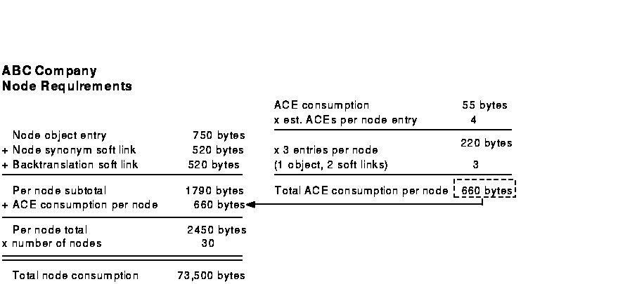
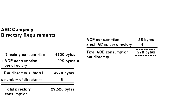
Given that all of their nodes would be named in the root, and that most of their node names would not exceed 10 or 12 characters, the planners thought that the estimate of 20 bytes required for a principal was high. They decided to reduce the estimate for principals to 15 bytes, thus reducing the total storage requirements for ACEs to 55 bytes each. They estimated an average of four ACEs on each directory and entry in the namespace. They also estimated that the server needs an additional 134,000 bytes for swap space for ULTRIX. Based on these considerations, the ABC Company planners produced the following node and directory capacity worksheets:
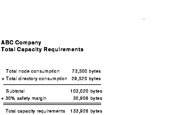
The planners then added the node total and the directory total and factored in a 30 percent margin of safety, as shown in the following worksheet:
As a final step in capacity planning for ULTRIX or Digital UNIX systems, the planners estimated that the server needs an extra 134,000 bytes for swap space and the clearinghouse database needs 268,000 bytes in the /usr/var/dss/dns partition. For OpenVMS VAX systems, the planners estimated that they need a minimum of 525 blocks in the DNS$SERVER default directory.
International Air Freight (IAF) Corporation is a hypothetical air freight company that does business in the United States, Europe, and Japan. The company plans to expand into other countries in the near future and anticipates considerable growth in its network.
The company consists of a New York office and a Chicago office. The New York office is corporate headquarters and is also the base for IAF's sales organization. A small engineering group in New York develops and maintains software applications specific to the company's business and distribution needs. Chicago is the hub of IAF's distribution operations. Also in Chicago is a small engineering and manufacturing group. This group designs and manufactures the packaging that IAF uses to transport freight.
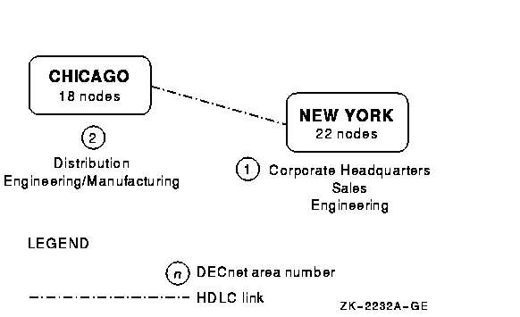
The IAF network currently consists of 22 DECnet nodes on a local area network (LAN) in New York and 18 DECnet nodes on a LAN in Chicago. The two LANs are connected by DEC WANrouters that are communicating by means of a High-level Data Link Control (HDLC) link. DECnet-Plus software is in use, and the hardware includes workstations, personal computers, and large VAX systems. DECdns servers are running on DECnet-Plus for ULTRIX and DECnet-Plus for OpenVMS VAX systems. Figure 9-1 is a representation of the IAF network.
Figure 9-1 The IAF Network
IAF's introduction to DECdns came when the company decided to upgrade its network to DECnet Phase V. Network administrators learned that DECnet-Plus Session Control can use DECdns to store and look up node names. They saw the ability to distribute node names, combined with the automatic updating capability of DECdns, as a time and resource saver. In the beginning, DECnet would be the primary user of DECdns and node names would be the primary entries in the namespace. The Digital Distributed Time Service (DECdts), another component of DECnet-Plus, would use DECdns to store the names of global servers that synchronize system clocks in the network.
When planning for DECdns, IAF anticipated future use by applications in addition to those that would be in place immediately after the transition to DECnet-Plus. Other client applications that IAF planned to use included Digital's VAX Distributed File Service (DFS), VAX Notes, and Remote System Manager (RSM), products that use Version 1 of the name service.
IAF engineers also planned to develop their own client applications specific to the company's distribution, manufacturing, and administrative needs. For instance, IAF had a real-time application that collected data on the location and flight times of air carriers and tracked the status of freight at each of the company's distribution sites. The application used a message bus for task-to-task communications and message queuing. The message bus, in turn, would be adapted to store the names and addresses of its message queues in DECdns.
IAF assembled a planning committee to plan the transition from DECnet Phase IV to DECnet-Plus and to plan the DECdns namespace. The committee decided to make a staged DECnet transition. First, they would upgrade a portion of their LAN in New York and configure two DECdns servers there. Six to eight months later, they would begin to upgrade the Chicago LAN, configuring two DECdns servers there as well. Transition of the remaining nodes in New York would be gradual, as time and resources allowed.
This chapter discusses decisions the IAF planners made in designing and
configuring their namespace. It also describes some of the business
changes the company went through after initially setting up its
namespace, and explains the effects those changes had on the namespace.
The discussion refers to other manuals or other chapters in this manual
for more information on some of the activities described.
9.1 Part 1: Planning and Configuring the Namespace
The planning committee chose a namespace nickname based on the initials that stand for the company's name: IAF. For naming clearinghouses, the committee decided to identify a clearinghouse by the city where it was located and adopted the recommended convention of adding a _CH suffix to a name. They knew they would have fewer than 50 clearinghouses, so they also followed the recommendation for naming all clearinghouses in the root directory. For example, clearinghouses in New York would be called .NY1_CH and .NY2_CH.
Next, the committee decided to assess the size and contents of the IAF namespace to determine whether they needed to create a directory structure. They knew that, for DECnet-Plus, every node in the network would have three entries in the namespace: an object entry and two soft links. After considering the needs of other applications, the committee produced the following list of projected namespace contents:
It was clear that node names and soft links would have the most
significant impact on the namespace; the number of names created by
other applications would be minimal. Even the impact of node names and
soft links would be minimal in a network the size of IAF's. However,
the company and its network were expected to grow. Therefore, the
planning committee decided to prepare for future expansion by designing
a directory hierarchy.
9.1.1 Designing the Directory Structure
The committee decided that creating several directories, all one level below the root, would be more than sufficient to handle the size of the IAF namespace. They wanted to avoid the longer names and the additional management tasks associated with multiple directory levels. They also felt confident that it would be a long time before any one directory contained more than 5000 names: a number that they considered a practical directory size limit.
The planners decided on a functional directory naming scheme. The decision was easy, because IAF is a functionally oriented organization. Resources, including nodes, are allocated and managed on a departmental basis, regardless of geographic location. For that reason, the company's organization chart could serve as a template both for the directory structure and for designing an access control policy.
Using the organization chart, the committee planned functional directories for administration, engineering, distribution, and sales, resulting in the hierarchy shown in Figure 9-2.
Figure 9-2 IAF Namespace Hierarchy
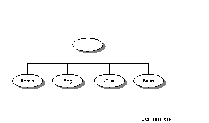
The namespace access control policy would be closely tied to the directory structure. The committee decided to implement a policy of world read and test access on the entire namespace, but to limit other access rights for each functional directory to the main users and managers of the names in those directories. They would use DECdns access control groups to implement this policy.
The .DNS_Admin group, a namespacewide administrative group, would consist of the network manager, who was the designated namespace administrator, and other staff members from IAF's Network Control Center. The members of the .DNS_Admin group would be the only people with full access to the root directory. The planners also decided to give the group access that propagates down to all subsequent directories and their contents. The propagating access would allow the .DNS_Admin group members to monitor any changes or problems in the namespace.
The .DNA_Registrar group is an access control group created during configuration of the first DECnet-Plus node in the namespace. Its purpose is to contain the names of people responsible for managing node object entries and soft links. The planners had read the DECnet transition documentation and decided to use this group as well. They decided to make the .DNS_Admin group a member of the .DNA_Registrar group, automatically granting the namespacewide administrators access to all node-related entries in the namespace. Additionally, the .DNA_Registrar group would contain the names of people at each site who were traditionally responsible for assigning and monitoring node names.
In addition to the .DNS_Admin and .DNA_Registrar
groups, the planners decided to create separate access control groups
to manage each functional directory. The directory management groups
would be named .Admin.Dir_Admin, .Sales.Dir_Admin,
.Eng.Dir_Admin, and .Mfg.Dir_Admin. Each group would have
full access to the contents of the directory it was associated with,
and would contain the names of the current managers of that directory.
With groups as the main method of granting access control, the
namespacewide administrative group could simply add and remove members
of a group instead of creating and deleting individual ACEs whenever
management responsibility for a directory changed.
9.1.3 Assessing Directory Contents
Based on their decisions, the planners outlined the contents of each directory as follows:
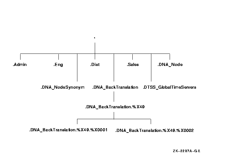
In addition, the following directories would be created during or soon after configuration of the first DECnet-Plus node:
With these additional directories added into the hierarchy, the complete picture of the namespace would look like the one in Figure 9-3. The shaded areas separated by white lines indicate levels of the hierarchy.
Figure 9-3 Complete IAF Namespace Hierarchy
The committee could see that, at least in the initial stages of DECdns
usage, the sales and engineering directories and the node soft link
directories would be the most heavily populated. However, the planners
were not concerned that some directories would be larger than others.
They knew that load balancing is determined not by directory size but
by the number of servers in the namespace and how directories are
replicated on those servers. Additionally, in such a small namespace,
none of the directories would contain enough entries to have
significant impact relative to any other directory.
9.1.4 Choosing Servers and Planning Replication
The next step for the committee was to plan how they were going to replicate directories and how many DECdns servers they would need.
After considering the guidelines in Chapter 8, the planners decided to configure two servers on the New York LAN and two servers on the Chicago LAN. The clearinghouses at the two New York servers would both contain an identical set of directory replicas. The planners felt this replication scheme would help to reduce confusion during the initial configuration of DECdns in the network. They also knew it would help to balance the work load between the two servers, increase the likelihood of finding a name without going off the LAN, and provide automatic, real-time backup of data in case a clearinghouse or replica became corrupted or temporarily unavailable.
The committee selected systems based on estimates of 1 MIPS of CPU power, 3,000 disk blocks, and 1 megabyte (2,000 pages) of memory required to run DECdns in the IAF network. In choosing the first server to be configured in New York, the committee also considered additional requirements, because that system would be the first system in the network to make the transition to DECnet-Plus. Table 9-1 indicates the systems selected to be DECdns servers.
| Clearinghouse Name | Server Hardware |
|---|---|
| .NY1_CH | VAX 6310 |
| .NY2_CH | VAXstation 3500 |
| .Chicago1_CH | DECsystem 5400 |
| .Chicago2_CH | DECstation 3100 |
![[HR]](../../IMAGES/REDBAR.GIF)
  PLAN_PROFILE_009.HTML
  OSSG Documentation
   2-DEC-1996 12:32:17.52
Copyright © Digital Equipment Corporation 1996. All Rights Reserved.