![[Digital logo]](../../IMAGES/DIGITAL-LOGO.GIF)
![[HR]](../../IMAGES/REDBAR.GIF)
DECnet-Plus
Network Control Language Reference
Previous
| Contents
Arguments:
|
frame
|
Contents of the header of the received FRMR frame.
|
|
frame reject reason
|
Why the frame was rejected. See possible reasons described under the
frame reject reason argument of the
frame reject generated event.
|
link halted
Generated when the status attribute protocol state is set to
halted.
Argument:
|
link halted reason
|
Why the protocol halted.
|
|
|
disc
|
A DISC frame was received. The remote end has disconnected the link.
|
|
|
dm
|
A DM frame was received. The remote end has disconnected the link.
|
|
|
frmr
|
A FRMR frame was received. The remote end has detected a frame error.
|
|
|
implementation specific
|
The cause is unknown.
|
|
|
LAN
|
The LAN station has failed.
|
|
|
local
|
Local management action on the
sap or
link entities has halted the link.
|
|
|
maximum retry
|
A PDU had to be retransmitted the maximum number of times without
response from the remote end.
|
|
|
user
|
Local client action has halted the link.
|
link initializing
Generated when the protocol has been successfully initialized or
reinitialized.
Argument:
|
link initializing reason
|
Why the protocol was initialized or reinitialized. See possible reasons
described under the
link halted reason argument of the
link halted event.
|
link inoperative
Generated when the status attribute protocol state is set to
inoperative.
link resetting
Generated when the status attribute protocol state is set to
resetting.
Argument:
|
link resetting reason
|
Why the protocol is being reset.
|
|
|
frmr
|
A FRMR frame was received. The remote end has detected a frame error.
|
|
|
implementation specific
|
The reason is unknown.
|
|
|
maximum retry
|
A PDU had to be retransmitted the maximum number of times without
response from the remote end.
|
|
|
sabme
|
A SABME frame was received. The remote end has reset the link.
|
link running
Generated when the status attribute protocol state is set to
running. This means that the protocol has been successfully
initialized or reset.
link setup failure
Generated when LLC2 protocol initialization has failed after the
maximum number of retries.
link state changed
Generated when the status attribute state changes from
on to off, or from off to on.
14.4.6 Exception Messages
For enable:
client data size not supportable
The data size specified by a client that has opened an LLC2 port to use
this link cannot be supported.
link data size not supportable
The data size specified by the characteristic maximum data
size cannot be supported by the SAP that owns this link.
remote address in use
The remote MAC address and remote link service access point (hex-number
LSAP) address are already being used by another link.
Chapter 15
Loopback Application Module
The Loopback Application module allows a network manager to invoke a
loopback test between applications on two nodes, thus testing all the
supporting layers of the Digital Network Architecture (DNA).
The Loopback Application module has two components:
- The loop access module, which initiates the loopback test.
- The loop mirror module, which accepts connections from the remote
loop access modules and mirrors any data sent to it back to the sender.
Figure 15-1 shows the hierarchical relationship of the entities that
constitute the Loopback Application module.
Figure 15-1 Hierarchy of Loopback Application Module
Entities

15.1 loopback application
The loopback application entity describes features of the
Loopback Application module which allows you to run a loopback test
between two nodes or itself. The loopback application entity
is created and deleted automatically with the node entity, and
is always enabled.
loop [node node-id] loopback application
{address tower-set | count integer | format
hex-string | length integer | maximum data | maximum
mirrors integer | name full-name }
set [node node-id] loopback application
{maximum mirrors integer}
show [node node-id] loopback application [all
[attributes] | all characteristics ]
15.1.1 Commands
loop
Starts a loop test between the loopback applications on the specified
source and destination nodes. The node keyword specifies the
node from which the loop messages are sent. If you omit this keyword,
the test is performed from the node on which you issue the loop
command. The name or address argument specifies
the node whose loop mirror is used to reflect the messages back to the
originator. Specify either the name or address (but
not both).
15.1.2 Characteristic Attributes
address tower-set
Number of the destination for loopback messages, in the form of a
protocol tower. Specify either this argument or the name
argument.
count integer
|
Default: 1
|
Value: 0--4294967295
|
Number of loop messages to be sent to the loop mirror. The test is
complete when this number of loop messages has been reflected back by
the loop mirror.
format hex-string
|
Default: 55
|
Value: 00--FF
|
Content of the data field of a loop message. Enter a pair of
hexadecimal digits. Each octet in the data field of a loop message has
this value.
length integer
|
Default: 40
|
Value: 0--65534
|
Length, in octets, of the data field in each loop message.
maximum data
The maximum size, in octets, of the loop message data field that the
loop mirror can reflect. If the loop mirror receives a loop message
with a longer data field, an error occurs.
For Digital UNIX, to limit the number of loop mirrors, use the
maximum instances characteristic of the session control
application mir entity.
maximum mirrors integer
|
Default: 0
|
Value: 0--4294967295
|
Enter the maximum number of loop mirrors supported. If you enter the
value 0, the node supports an unlimited number of mirrors.
For Digital UNIX, to limit the number of loop mirrors, use the
maximum instances characteristic of the session control
application mir entity.
name full-name
DNS name of the node to which loopback messages are sent. Specify
either this argument or the address argument, but not both.
15.1.3 Exception Messages
For loop:
bad data at mirror
There has been an error in the loopback protocol. The possible errors
are:
- The local node sent a loop message with a data field that was too
long.
- The first octet of the loop message was corrupted when it arrived
at the mirror module.
Arguments:
|
count
|
Requested number of messages in the loopback test (that is, the value
of the
count argument).
|
|
message number
|
Number of the loop messages in which the error occurred.
|
|
start time
|
Time at which the loopback test began.
|
both name and address specified
Both the name and address arguments have been
specified. You must specify one of these arguments, but not both.
connection failed
The Session Control connection to the loop mirror failed.
Arguments:
|
reason
|
Reason why the connection failed. This is the reason code provided by
Session Control.
|
|
start time
|
Time the loopback test began.
|
data returned differs from data sent
The data field in a loop message reflected back by the loop mirror is
not the same as the data field in the loop message that was sent.
Arguments:
|
count
|
Requested number of messages in the loopback test (that is, the value
of the
count argument).
|
|
format
|
Value for each octet of the data field of the loop message (that is,
the value of the
format argument).
|
|
length
|
Length of the data field of the loop message, as requested by the
length argument.
|
|
message number
|
Number of the loop message in which the error occurred.
|
|
message returned
|
Contents of the reflected loop message.
|
|
start time
|
Time the loopback test began.
|
disconnected
The link to the loop mirror was disconnected before the loopback test
was completed.
Arguments:
|
count
|
Requested number of messages in the loopback test (that is, the value
of the
count argument).
|
|
message number
|
Number of the loop message in which the error occurred.
|
|
reason
|
Reason why the link was disconnected. This is the reason code returned
by Session Control.
|
|
start time
|
Time the loopback test began.
|
length too long
The requested length of the data field is greater than the maximum data
field length that the loop mirror can handle.
Arguments:
|
length
|
Data field length requested, in octets.
|
|
maximum data
|
Maximum data field length supported by the loop mirror.
|
|
start time
|
Time at which the loopback test began.
|
neither name nor address specified
You have not specified the name or the address
argument. You must specify one of these arguments, but not both.
Chapter 16
Modem Connect Module
This chapter describes all the commands you can use to manage the
entities that constitute the Modem Connect module. The Modem Connect
module implements one of the protocols in the Physical layer described
by the Digital Network Architecture (DNA).
Note
For Digital UNIX, the Digital WAN Device Drivers product is provided as
an installable subset within the product X.25 for Digital UNIX systems.
You must install this subset before you can refer to the LAPB module
entities in an NCL command.
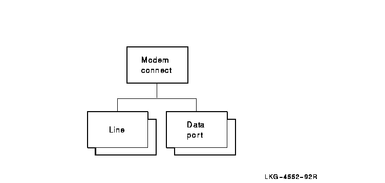
Figure 16-1 shows the hierarchical relationship of the entities that
constitute the Modem Connect module.
Figure 16-1 Hierarchy of Modem Connect Module Entities
16.1 modem connect
The modem connect entity is the top-level entity in the
hierarchy of entities belonging to the Modem Connect module.
create [node node-id] modem connect
delete [node node-id] modem connect
show [node node-id] modem connect [all
[attributes] | all characteristics ]
16.1.1 Characteristic Attributes
DNA version
Version number of the DNA Modem Connect architecture to which the
implementation conforms. You cannot modify this characteristic.
16.2 modem connect data port
The modem connect data port entity is associated with a line
and handles the transfer of data. Data ports are created and deleted
automatically when a client of the Modem Connect module uses a line.
The port-name refers to data port managed by this command.
show [node node-id] modem connect data port
port-name [all [attributes] | all identifiers | all status ]
16.2.1 Identifier Attributes
name
Simple name assigned to the data port when it is created.
16.2.2 Status Attributes
client
Name supplied by the client when the port was opened. This defines
which client owns the port.
line
Name of the modem connect line entity that the client supplied
when the port was opened.
state
State of data port.
|
open
|
The port is assigned to a client.
|
|
open disabled
|
The port is assigned to a client, but the line entity that port refers
to is disabled.
|
16.3 modem connect line
A modem connect line entity is associated with a physical
circuit on the node. Usually, there is one line entity for each
circuit. The line-name refers to the line managed by this
command.
add [node node-id] modem connect line
line-name modem options [set]
create [node node-id] modem connect line
line-name {communications mode comm-mode |
communication port port-name | connection type
conn-type (Digital UNIX) | duplex full-or-half |
profile profile-name | rate select rate (OpenVMS) }
delete [node node-id] modem connect line
line-name
disable [node node-id] modem connect line
line-name
enable [node node-id] modem connect line
line-name
remove [node node-id] modem connect line
line-name modem options [set]
set [node node-id] modem connect line
line-name {alternate speed bits-per-second | call
accept timer milliseconds | carrier loss timer
milliseconds | clock clock-source | encoding
normal-nrzi | initial hold timer seconds (Digital
UNIX) | maximum call setup timer seconds | maximum disable
transmit timer milliseconds | maximum dsr de-assertion timer
milliseconds | maximum enable transmit timer
milliseconds | minimum dtr de-assertion timer
milliseconds | modem control [full or none] | modem options
[modem-option] | modem protocol format type (Digital
UNIX) | modem protocol type prot-type (Digital UNIX) | rate
select [high or low] | speed bits-per-second | successful call
indication timer seconds | suppress test indicator
boolean | transmit holdoff timer milliseconds }
show [node node-id] modem connect line
line-name mode [all [attributes] | all characteristics | all
counters | all identifiers | all status ]
startloop [node node-id] modem connect line
line-name mode {driver or device | local or remote | connector
or external }
stoploop [node node-id] modem connect line
line-name
16.3.1 Commands
startloop
Causes a Physical layer to place the line in loopback mode.
stoploop
Opens a previously closed Physical layer loop to take it out of
loopback mode.
16.3.2 Arguments
communications mode mode
Communications method used on the link. This argument determines the
value of the communications mode characteristic. The default
value is taken from the device capability. If that is unknown, the
default is synchronous.
communications port port-name
Name of the communications port to which the communications line is
connected. This argument determines the value of the communications
port characteristic and is required.
duplex duplex
Specifies whether the line is full-duplex or half-duplex. This argument
determines the value of the duplex characteristic. The default
value is taken from the device capability. If that is unknown, the
default is set to full.
mode mode
Method of startloop used on line.
|
connector
|
Data is looped through a loopback connector attached to the
communications device.
|
|
device
|
Data is looped in the communications device.
|
|
driver
|
Data is looped in the driver of the communications device.
|
|
external
|
Data is looped through a null modem or a modem in loopback mode.
|
|
local
|
Communications device has switched its local modem into loopback mode.
|
|
null
|
Line is not in loopback mode. This argument only applies to Digital
UNIX.
|
|
remote
|
Communications device has switched the remote modem into loopback mode.
|
profile latin1string
Name of a local profile to be used with the line. This argument
determines the value of the profile characteristic.
16.3.3 Characteristic Attributes
alternate speed
Alternate (low) speed, in bits per second, to operate the line. You can
modify this characteristic only when the entity is disabled. This
characteristic is supported only when the characteristic
communications mode is asynchronous, the
characteristic modem control is full, the
characteristic modem options includes rateselect, the
characteristic clock is internal, and when the
alternate line speed is needed.
call accept timer
Minimum time, in milliseconds, between the assertion of data set
ready and accepting a call by asserting request to send.
This attribute is maintained only if the characteristic modem
control is set to none.
carrier loss timer
Maximum time, in milliseconds, that the carrier detect signal
can be absent before the loss of carrier event is generated.
This attribute is not supported if the characteristic modem
control is set to none.
clock
Source of the transmit and receive clocks.
|
external
|
The modem provides the clock.
|
|
internal
|
The communications device provides the clock.
|
|
reflected
|
The DTE transmit clock is a reflection of the DCE transmit clock. This
minimizes the clock to data skew that the DCE encounters when high line
speeds are used.
|
The default value depends on the setting of the characteristic
communications mode. If communications mode is
asynchronous, the default value of this characteristic is
internal. Otherwise, the default value is external.
The value of this attribute has no effect when the communications line
is in loopback mode. In this case, the type of loopback determines the
type of clock. This characteristic can only be modified when the entity
is disabled.
communications mode
|
Default: Synchronous
|
Value: Asynchronous or synchronous
|
Communications method to be used on the line. The value of this
characteristic is a copy of the communications mode argument
specified when the entity is created. You cannot modify this
characteristic.
communications port
Name of the communications port. The value of this characteristic is a
copy of the communications port argument specified when the
entity is created.
connection type (Digital UNIX)
|
Default: Nonswitched
|
Value: Nonswitched or switched
|
Indicates whether the line is switched or
nonswitched. The value of this characteristic is a copy of the
connection type argument specified when the entity is created.
You cannot modify this characteristic.
duplex
|
Default: Full
|
Value: Full or half
|
Indicates whether the line is full- or half-duplex.
The value of this characteristic is a copy of the duplex
argument specified when the entity is created.
encoding
|
Default: Normal
|
Value: Normal or nrzi
|
Encoding technique used on the line. This characteristic can only be
modified when the entity is disabled.
initial hold timer (Digital UNIX)
Maximum time, in seconds, that the entity waits for an incoming call to
be accepted.
maximum call setup timer (Digital UNIX)
Maximum time, in seconds, that the entity waits for the outgoing call
to connect.
maximum disable transmit timer
|
Default: 500
|
Value: 0--60000
|
Maximum time, in milliseconds, that clear to send can remain
asserted before the line is disconnected after request to send
is de-asserted. This attribute is not supported if the characteristic
modem control is set to none.
maximum dsr de-assertion timer
|
Default: 5000
|
Value: 0--60000
|
Maximum time, in milliseconds, the entity will wait for data set
ready to be de-asserted after it has de-asserted data terminal
ready. If this timer expires, the entity assumes it can assert
data terminal ready once again. This attribute is not
supported if the characteristic modem control is set to none.
maximum enable transmit timer
|
Default: 2000
|
Value: 1--5000
|
Maximum time, in milliseconds, between the assertion of the request
to send signal and receiving the assertion of the clear to
send signal. This attribute is not supported if the characteristic
modem control is set to none.
minimum dtr de-assertion timer
|
Default: 1000
|
Value: 0--60000
|
Minimum time, in milliseconds, that the DTE will de-assert data
terminal ready during a disconnection. This attribute is not
supported if the characteristic modem control is set to none.
modem control
|
Default: Full
|
Value: Full or none
|
Indicates whether the interchange circuits are to be monitored and
used. The value none means that only the data leads are
monitored.
The value full must be used when the value of the
characteristic duplex is half. This characteristic is
supported only if the characteristic connection type is
switched.
modem options
|
Default: No options
|
Value: Set of options
|
Set of values that determine the capabilities of the modem.
|
dialout
|
The modem can dial the remote modem. Supported only if the value of
communications type is
switched. This value is supported by Digital UNIX only.
|
|
direct
|
The modem is directly connected to the remote modem through a
nonswitched line. Supported only if accompanied with
dialout and used only when the
modem protocol type supports direct dial. This value is
supported by Digital UNIX only.
|
|
rate select
|
The modem is capable of data rate selection.
|
modem protocol format (Digital UNIX)
|
Default: See description
|
Value: See description
|
Format to use for V.25bis protocol messages. This characteristic
applies only when the characteristic modem protocol type is
v25bis or dmcl.
|
asynchronous
|
Use the asynchronous format.
|
|
hdlc
|
Use the HDLC format.
|
|
synchronous
|
Use the synchronous format.
|
Previous
| Next
| Contents
| [Home]
| [Comments]
| [Ordering info]
| [Help]
  NCL_PROFILE_013.HTML
  OSSG Documentation
   2-DEC-1996 12:48:05.35
Copyright © Digital Equipment Corporation 1996. All Rights Reserved.
Legal