![[HR]](../../IMAGES/REDBAR.GIF)
# dbx -k /vmunix
dbx) p r1006_allocb_failures
0
dbx)
This chapter describes how to use routing circuit and data link information to isolate and correct simple DECnet-Plus network layer problems.
Topics In This Chapter
The topics in this chapter are:
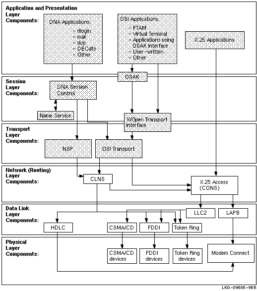
8.1 Underlying Entities (OpenVMS Only)
To isolate problems at the Network layer, you need to be able to
identify the data link entities that the Routing layer uses and the
physical entities associated with the data link entities.
Figure 8-1 illustrates the users of the data links that you find in a DECnet-Plus for OpenVMS system.
Figure 8-1 Underlying Entities (OpenVMS)

8.2 Underlying Entities (Digital UNIX Only)
To isolate problems at the Network layer, you need to be able to
identify the data link entities that the Routing layer uses and the
physical entities associated with the data link entities.
Figure 8-2 illustrates the users of the data links that you find in a DECnet-Plus for Digital UNIX system.
Figure 8-2 Underlying Entities (Digital UNIX)
8.3 Symptoms of Network Layer Problems
The symptoms in Table 8-1 indicate that a routing-circuit or data
link problem exists.
| Symptom | Possible Problem | See |
|---|---|---|
|
Entities were not available when tracing a path between a routing
circuit and the physical device.
One or more of the entities had a State characteristic set to off. An error appeared when you tried to enable an entity. |
Configuration | Section 8.6 |
| An application failed but no errors were found in the upper layers | Configuration or connectivity | Section 8.6 or 8.7 |
| The configuration is correct but the routing circuit does not work | Connectivity | Section 8.7 |
If you think you have a Network layer problem, first check the physical
connections between systems before you examine routing circuits and
their underlying entities.
8.4.1 Tools to Use
Use NCL commands to check routing circuits in the Network layer.
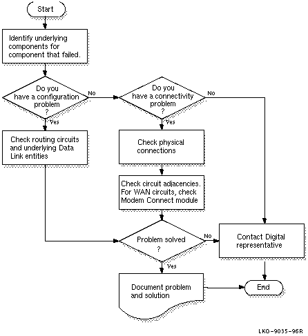
8.4.2 Fault-Isolation Methodology
Use Figure 8-3 as a guideline when you isolate circuit connectivity
and configuration faults. The following sections in this chapter
describe related correction procedures.
Figure 8-3 Fault-Isolation Methodology (Circuit Connectivity)
8.5 Finding Underlying Entities
To isolate routing circuits and data link problems in the Network
layer, you need to be able to identify the underlying entities for
specific routing circuits.
For each routing circuit type, there is a corresponding data link
entity displayed with the set of circuit characteristics. The X.25
Protocol module provides information about the associated data link
entities for X.25 circuits. Refer to your NCL and X.25 documentation
for more details about X.25 circuits.
8.5.1 Finding the Underlying Entities for HDLC Circuits
If you know the routing circuit ID, you can identify the associated underlying entities, including the physical device entity by doing the following:
| Step | Action |
|---|---|
| 1 | Set the NCL default entity to the node whose circuits you want to check. If you cannot reach a remote node over the network, log into that system directly to check the circuits. |
| 2 |
Find the data link entity for the routing circuit that you want to
check. Use the following NCL command:
ncl>show routing circuit
circuit-id -
|
| 3 |
Examine the physical line characteristic of the data link entity
module. Use the following NCL command:
ncl>show hdlc link link-name logical station |
| 4 |
Examine the physical device entity to identify the communications
device. Use the following NCL command:
ncl>show modem connect line
line-id -
|
If you know the physical device entity, you can identify the associated routing circuit by doing the following:
| Step | Action |
|---|---|
| 1 |
Find the Modem Connect entity connected to the physical device. Use the
following NCL command:
ncl>show modem connect line * comm port |
| 2 |
Examine the Modem Connect data port entity for the communications port.
Use the following NCL command:
ncl>show modem connect data port * all status |
| 3 |
Examine the HDLC port entity's attributes for one that contains the
same client as displayed in the previous step. The client
characteristic indicates the routing circuit. Use the following NCL
command:
ncl>show HLDC port * all status |
8.5.3 Finding the Underlying Entities for DDCMP Circuits (OpenVMS Only)
If you know the routing circuit ID, you can identify the associated
underlying entities, including the physical device entity by doing the
following:
| Step | Action |
|---|---|
| 1 | Set the NCL default entity to the node whose circuits you want to check. If you cannot reach a remote node over the network, log into that system directly to check the circuits. |
| 2 |
Find the data link entity for the routing circuit that you want to
check. Use the following NCL command:
ncl>show routing circuit
circuit-id -
|
| 3 |
Examine the physical line characteristic of the data link entity
module. Use the following NCL command:
ncl>show ddcmp link link-name physical line |
| 4 |
Examine the physical device entity to identify the communications
device. Use the following NCL command:
ncl>show modem connect line line-id comm port |
If you know the physical device entity, you can identify the associated routing circuit by doing the following:
| Step | Action |
|---|---|
| 1 |
Find the Modem Connect entity connected to the physical device. Use the
following NCL command:
ncl>show modem connect line * comm port |
| 2 |
Examine the Modem Connect entity for the communications port. Use the
following NCL command:
ncl>show modem connect data port * all status |
| 3 |
Examine the DDCMP port entity's attributes for the client
characteristic. The client characteristic indicates the routing
circuit. Use the following NCL command:
ncl>show DDCMP port * all status |
If you know the routing circuit ID, you can identify the associated underlying entities, including the physical device entity by doing the following:
| Step | Action |
|---|---|
| 1 | Set the NCL default entity to the node whose circuits you want to check. If you cannot reach a remote node over the network, you need to log into that system directly to check the circuits. |
| 2 |
Find the data link entity. Use the following NCL command:
ncl>show routing circuit
circuit-id -
|
| 3 |
Examine the communication port characteristic of the data link entity
to identify the communications port. Use the following NCL command:
ncl>show csma-cd station station-id comm port |
If you know the physical device entity, you can identify the associated routing circuit by doing the following:
| Step | Action |
|---|---|
| 1 |
Find the CSMA-CD station entity connected to the physical device. Use
the following NCL command:
ncl>show csma-cd station * comm port |
| 2 |
Examine the CSMA-CD port entity's attributes to find the routing
circuit. Use the following NCL command:
ncl>show csma-cd port * client,station |
If you know the routing circuit ID, you can identify the associated underlying entities, including the physical device entity by doing the following:
| Step | Action |
|---|---|
| 1 | Set the NCL default entity to the node whose circuits you want to check. If you cannot reach a remote node over the network, log into that system directly to check the circuits. |
| 2 |
Find the data link entity for the routing circuit that you want to
check. Use the following NCL command:
ncl>show routing circuit
circuit-id -
|
| 3 |
Examine the physical port characteristic of the data link entity to
identify the physical port. Use the following NCL command:
ncl>show fddi station
station-id -
|
If you know the physical device entity, you can identify the associated routing circuit by doing the following:
| Step | Action |
|---|---|
| 1 |
Find the FDDI station entity connected to the physical device. Use the
following NCL command:
ncl>show fddi station * -
|
| 2 |
Examine the FDDI port entity's attributes to find the routing circuit.
Use the following NCL command:
ncl>show fddi port * client |
8.5.9 Finding the Underlying Entities for Token Ring Circuits (Digital UNIX Only)
If you know the routing circuit ID, you can identify the associated
underlying entities, including the physical device entity by doing the
following:
| Step | Action |
|---|---|
| 1 | Set the NCL default entity to the node whose circuits you want to check. If you cannot reach a remote node over the network, log into that system directly to check the circuits. |
| 2 |
Find the data link entity for the routing circuit that you want to
check. Use the following NCL command:
ncl>show routing circuit
circuit-id -
|
| 3 |
Examine the physical port characteristic of the data link entity to
identify the physical port. Use the following NCL command:
ncl>show token ring station
station-id -
|
If you know the physical device entity, you can identify the associated routing circuit by doing the following:
| Step | Action |
|---|---|
| 1 |
Find the Token Ring station entity connected to the physical device.
Use the following NCL command:
ncl>show token ring station * communication port |
| 2 |
Examine the Token Ring port entity's attributes to find the routing
circuit. Use the following NCL command:
ncl>show token ring port * client, station |
If you suspect there is a routing circuit configuration problem, check the routing circuit's state. If state=off, use the NCL command enable to set the state to on.
| If: | Then Do This: |
|---|---|
| Error appears | Check the characteristics of the data link entity associated with the routing circuit. |
| No error appears |
Check that the routing circuit state remains
on.
For HDLC circuits, if the state does not remain on, the system should generate an event indicating why. |
Do the following to correct problems with DDCMP or HDLC data links (only OpenVMS on Alpha systems support DDCMP entities):
| If: | Then Do This: |
|---|---|
| Error appears | Check the characteristics of the entity indicated in the error message. |
| No error appears |
Check that the state remains
on.
For HDLC circuits, if state does not remain on, check the Modem Connect module. |
| If Attribute Value Is: | Then: |
|---|---|
| Running | All devices and entities appear to be operating properly. |
| Starting or Initializing | The data link is attempting to connect with the remote system. If the link remains in this state for a significant amount of time, it could be that the data being transmitted is not received by the remote node. This indicates you have a connectivity problem. |
| Halted or Inoperative | One of the related entities is disabled. Check the states of the related entities. |
| Error | The threshold number of attempts to synchronize the link was reached. Check the counters for the logical station entity. |
Do the following to correct CSMA-CD data link configuration problems:
| Step | Action |
|---|---|
| 1 |
Check that the
CSMA-CD station exists. Use the following NCL command:
ncl>show csma-cd station station-id state |
| 2 |
If the device does not exist, issue the appropriate command to create
the device (see your installation documentation).
If an error appears when you try to create the device, check the entity specified in the message. |
| 3 |
If the device does exist, check the entity's state.
If the state is off, enable the device. If the state is on, and the data link still does not operate correctly, the cause is most likely a connectivity problem. |
If your configuration seems correct but the routing circuit does not work, it is possible that a connectivity problem is the cause of the failure. Do the following:
| Step | Action |
|---|---|
| 1 |
Check the physical connections. For example:
|
| 2 | For WAN links (HDLC), check the Modem Connect status to see if the modem control leads are asserted correctly. |
| 3 |
Determine if data is being sent and received. You can:
|
| 4 |
Look to see if circuit adjacencies exist. Use the following NCL command:
ncl>show circuit circuit-id * adjacency * all |
The OSAKtrace utility captures a record of what happens during an OSI information exchange. The OSAKtrace utility is not an implementation of any OSI standard; there is no ISO standard for OSI tracing.
You can use OSAKtrace to show that application programs that use the OSAK routines conform with the standards, and to identify any problems that may arise when one OSI application works with another over a network.
Information on using the OSAKtrace utility appears in OSAK Programming, and descriptions of the trace emitter calls appear in OSAK Programming Reference.
This appendix contains an example of a trace output for the FTAM and Virtual Terminal software.
The trace output for FTAM and Virtual Terminal operations on Digital UNIX and OpenVMS is very similar; this appendix shows the trace output as it appears on a Digital UNIX system.
B.1 DECnet-Plus Application Trace Example
This section provides an example of the default output of the
ositrace utility. This example traces the result of the FTAM
omv command on a Digital UNIX system.
B.1.1 Association Establishment --- Initiator
The initiator requests a session connection.
10:11:57.08     OSI trace started Wed Jan 30 10:11:57 1994

10:11:58.20 --> Session
        0dff0148 05061301 00160102 14020002 33028080 34020103 c1ff0130 3180a080
        80010100 00a28081 02808082 020103a4 80308002 01010605 28c27b02 01308006
        02510100 00000030 80020103 060528c2 7b020230 80060251 01000000 00308002
        01050605 28c27b02 03308006 02510100 00000030 80020107 060528c2 7b020430
        80060251 01000000 00308002 01090606 2bce0f01 02023080 06025101 00000000
        30800201 0b060452 01000130 80060251 01000000 00000088 02060089 03054000
        61803080 02010ba0 7b6080a1 80060528 c27b0101 0000a280 06052bce 0f070100
        00a38002 01010000 be802880 020101a0 4da08082 01008302 03408403 05070085
        02058086 0100a780 4e0528c2 7b05014e 0528c27b 05024e05 28c27b05 034e062b
        ce0f0105 09000056 0776696e 63656e74 710a1908 6e69636b 73746572 00000000
        00000000 00000000 00000000

        connect-spdu                                                    0d ff 01
            connect/accept-item                                         05 06
                protocol-options  = NULL                                13 01
                version-number  = 2                                     16 01 02
            session-user-requirements  = '0000000000000010'B            14 02 00
              ( duplex functional unit )
            calling-ssap-identifier  =                                  33 02 80
            called-ssap-identifier  =                                   34 02 01
            user-data                                                   c1 ff 01
Presentation Connection --- Initiator
The initiator requests a presentation connection. The negotiation of abstract syntaxes takes place during this time.
10:11:58.20 --> Presentation
        3180a080 80010100 00a28081 02808082 020103a4 80308002 01010605 28c27b02
        01308006 02510100 00000030 80020103 060528c2 7b020230 80060251 01000000
        00308002 01050605 28c27b02 03308006 02510100 00000030 80020107 060528c2
        7b020430 80060251 01000000 00308002 01090606 2bce0f01 02023080 06025101
        00000000 30800201 0b060452 01000130 80060251 01000000 00000088 02060089
        03054000 61803080 02010ba0 7b6080a1 80060528 c27b0101 0000a280 06052bce
        0f070100 00a38002 01010000 be802880 020101a0 4da08082 01008302 03408403
        05070085 02058086 0100a780 4e0528c2 7b05014e 0528c27b 05024e05 28c27b05
        034e062b ce0f0105 09000056 0776696e 63656e74 710a1908 6e69636b 73746572
        00000000 00000000 00000000 00000000

        CP PPDU SET =                                                   31 80
        {
          [0] IMPLICIT SET =                                            a0 80
          {
            [0] IMPLICIT mode-selector INTEGER = normal-mode            80 01 01
          }
          [2] IMPLICIT SEQUENCE =                                       a2 80
          {
            [1] IMPLICIT calling-presentation-selector OCTET STRING =   81 02
              '8080'H
            [2] IMPLICIT called-presentation-selector OCTET STRING =    82 02
              '0103'H
            [4] IMPLICIT presentation-context-definition-list           a4 80
              SEQUENCE =
            {
              SEQUENCE =                                                30 80
              {
                presentation-context-identifier INTEGER = 1             02 01 01
                abstract-syntax-name OBJECT IDENTIFIER =                06 05 28
                  {1 0 8571 2 1}
                SEQUENCE =                                              30 80
                {
                  transfer-syntax-name OBJECT IDENTIFIER = {2 1 1}      06 02 51
                }
              }
              SEQUENCE =                                                30 80
              {
                presentation-context-identifier INTEGER = 3             02 01 03
                abstract-syntax-name OBJECT IDENTIFIER =                06 05 28
                  {1 0 8571 2 2}
                SEQUENCE =                                              30 80
                {
                  transfer-syntax-name OBJECT IDENTIFIER = {2 1 1}      06 02 51
                }
              }
              SEQUENCE =                                                30 80
              {
                presentation-context-identifier INTEGER = 5             02 01 05
                abstract-syntax-name OBJECT IDENTIFIER =                06 05 28
                  {1 0 8571 2 3}
                SEQUENCE =                                              30 80
                {
                  transfer-syntax-name OBJECT IDENTIFIER = {2 1 1}      06 02 51
                }
              }
              SEQUENCE =                                                30 80
              {
                presentation-context-identifier INTEGER = 7             02 01 07
                abstract-syntax-name OBJECT IDENTIFIER =                06 05 28
                  {1 0 8571 2 4}
                SEQUENCE =                                              30 80
                {
                  transfer-syntax-name OBJECT IDENTIFIER = {2 1 1}      06 02 51
                }
              }
              SEQUENCE =                                                30 80
              {
                presentation-context-identifier INTEGER = 9             02 01 09
                abstract-syntax-name OBJECT IDENTIFIER =                06 06 2b
                  {1 3 9999 1 2 2}
                SEQUENCE =                                              30 80
                {
                  transfer-syntax-name OBJECT IDENTIFIER = {2 1 1}      06 02 51
                }
              }
              SEQUENCE =                                                30 80
              {
                presentation-context-identifier INTEGER = 11            02 01 0b
                abstract-syntax-name OBJECT IDENTIFIER = {2 2 1 0 1}    06 04 52
                SEQUENCE =                                              30 80
                {
                  transfer-syntax-name OBJECT IDENTIFIER = {2 1 1}      06 02 51
                }
              }
            }
            [8] IMPLICIT presentation-requirements BIT STRING = '00'B   88 02 06
              ( )
            [9] IMPLICIT user-session-requirements BIT STRING =         89 03 05
              '01000000000'B
              ( duplex )
            [APPLICATION 1] IMPLICIT fully-encoded-data SEQUENCE =      61 80
            {
              PDV-list SEQUENCE =                                       30 80
              {
                presentation-context-identifier INTEGER = 11            02 01 0b
                single-asn1-type [0] ANY =                              a0 7b

                -- Abstract Syntax Name
                --   ACSE-PCI
                -- Presentation Context Identifier
                --   11
ACSE Association Request --- Initiator
  PS_PROFILE_008.HTML
  OSSG Documentation
   2-DEC-1996 12:34:25.92
Copyright © Digital Equipment Corporation 1996. All Rights Reserved.